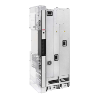
Overview of power and control connections
The diagram shows the power connections and control interfaces of the drive module.
L1
L2
L3
PE
U2
V2
W2
M 3 ~
L1
L2
L3
PE
9 11
10
ACS880-14
F
x
x
Slots 1, 2 and 3
..
..
X205
...
...
. . .
..
......
....
....
....
X12
X13
F
x
x
x
..
.......
.....
...
...
5
1 2 3
4
6
8
7
A
B
12
V1, V2,
V20, V21
V2, V7, V8, V13
UDC- UDC+
External control unit (motor-side converter control unit)A
Line-side converter control unitB
Analog and digital I/O extension modules, feedback interface modules and fieldbus communication
modules can be inserted into slots 1, 2 and 3. See Type designation key (page 41).
1
2
3
Connector for the FSO-xx safety functions module (X12). The module can be installed on or above the
control unit, see Installing the FSO-xx safety functions module (page 118).
4
Memory unit (see section Memory unit)
5
I/O terminal blocks. See chapter External control unit (page 121).
6
Control panel (see section Control panel)
7
Fiber optic link to the motor-side converter. Similarly, the line-side converter is connected to the line-side
converter control unit with fiber optic cables.
8
Line-side converter9
DC link10
Motor-side converter11
Socket for external line-side control unit control (not required for normal operation of the drive)12
40 Operation principle and hardware description

 Loading...