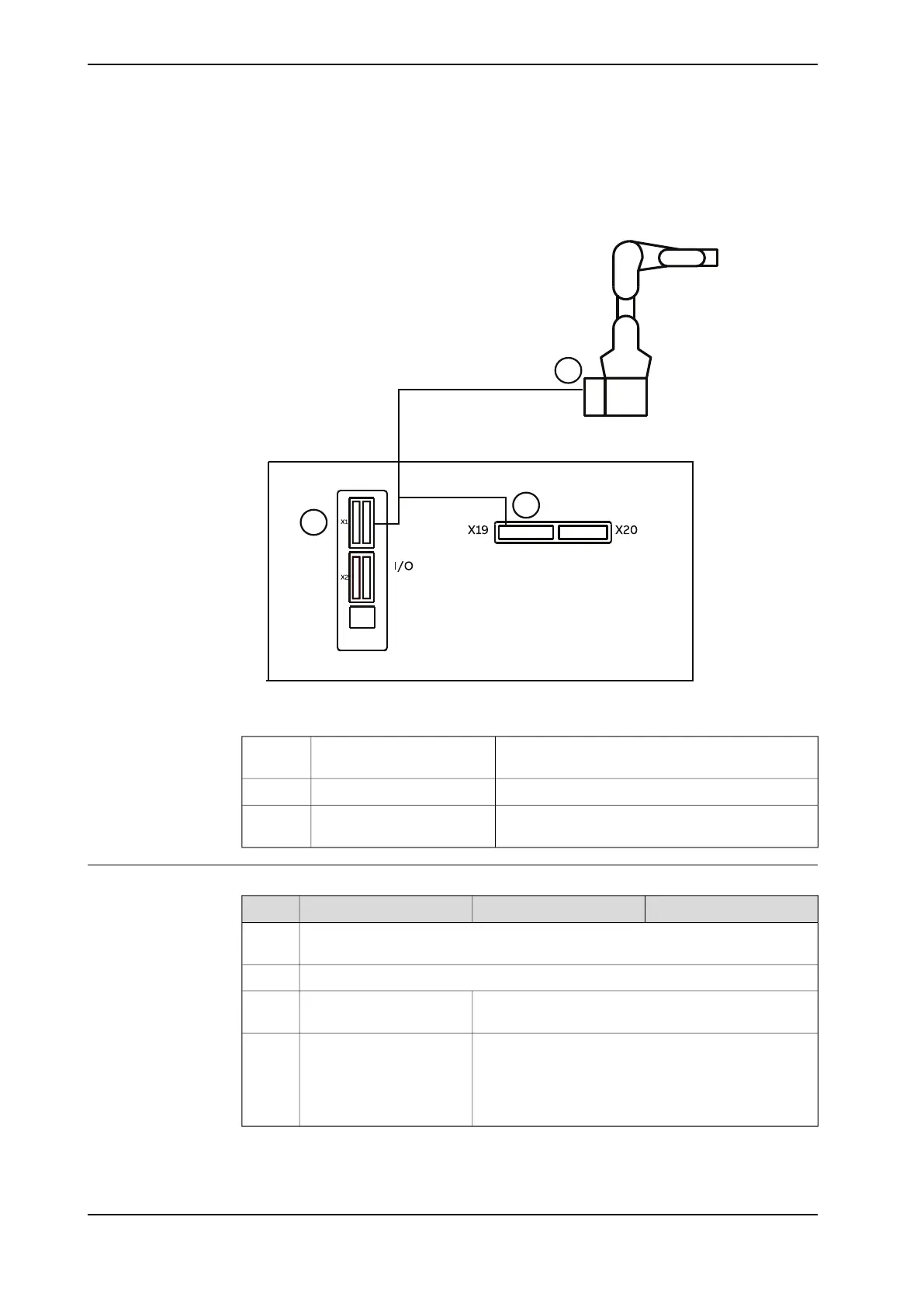
The following figure illustrates the lamp unit cabling connection between the
manipulator base and controller with base I/O module configured. For more details
about cabling, see the circuit diagram of the manipulator.
xx2200001159
Pins GND, DO1, DO2 and DO3 are occupied for
lamp unit
X1 connector on DSQC10301
Pins 1 and 2 are occupied for lamp unitX19 connector on controller2
R1.C1 connector on robot
base
3
Functionality
Manual full speed modeAutomatic modeManual modeColor
Standby (in motor on/off state and program is stopped, available for users to
perform next actions)
White
Program is executingGreen
Yellow warning area is triggered (manipulator speed
will be limited according to the actual configured value)
Lead-through function is
enabled
Yellow
Emergency stop, error is raised or red protecting area
is triggered.
Emergency stop or error is
raised
Red
For RobotWare 7.6 or later, the speed shown on the
FlexPendant remains but the manipulator will stand
still.
158 Product manual - CRB 1300
3HAC083111-001 Revision: B
© Copyright 2022-2023 ABB. All rights reserved.
3 Installation and commissioning
3.7.6 Robot status indication
Continued