3.5.2 Customer connections
Introduction to customer connections
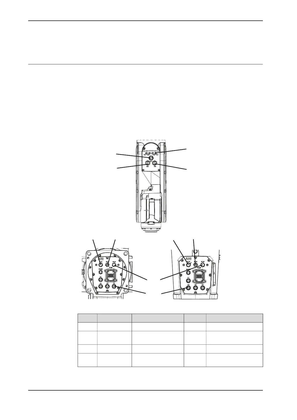
The cables for customer connection are integrated in the robot and the connectors
are placed on the tubular and one at the base. There are two connectors R2.C1
and R2.C3 at the tubular. Corresponding connectors R1.C1 and R1.C3 are located
at the base.
There is also connections for Ethernet, one connector R2.C2 at the tubular and
the corresponding connector R1.C2 located at the base.
Hose for compressed air is also integrated into the manipulator. There are 4 inlets
at the base (R1/8”) and 4 outlets (M5) on the tubular.
(A) (A)
(A)
(B)
(B)
(B)
(C)
(C)
(D)
(D)
xx2200000997
ValueNumberDescriptionConnectionPosition
30 V, 1.5 A12 wires
i
Customer power/signal(R1)R2.C1A
30 V, 1 A or 1 Gbits/s8 wires
ii
Customer power/signal
or Ethernet
(R1)R2.C2B
42 V DC or 25 V AC, 4 A
iii
4 wiresCustomer power/signal(R1)R2.C3C
Outer diameter of air hose:
6 mm
4Max. 6 barAirD
i
The connector has 12 pins. Only pins 5 to 12 are available for use. Pins 1 to 4 are used for LED
indicator.
Continues on next page
102 Product manual - CRB 1300
3HAC083111-001 Revision: B
© Copyright 2022-2023 ABB. All rights reserved.
3 Installation and commissioning
3.5.2 Customer connections