HVC 450 kW E-Bus Charger Installation Guide
Revision: 1.2 COMPANY CONFIDENTIAL
Date released: 16-08-2018 Page 100 of 128
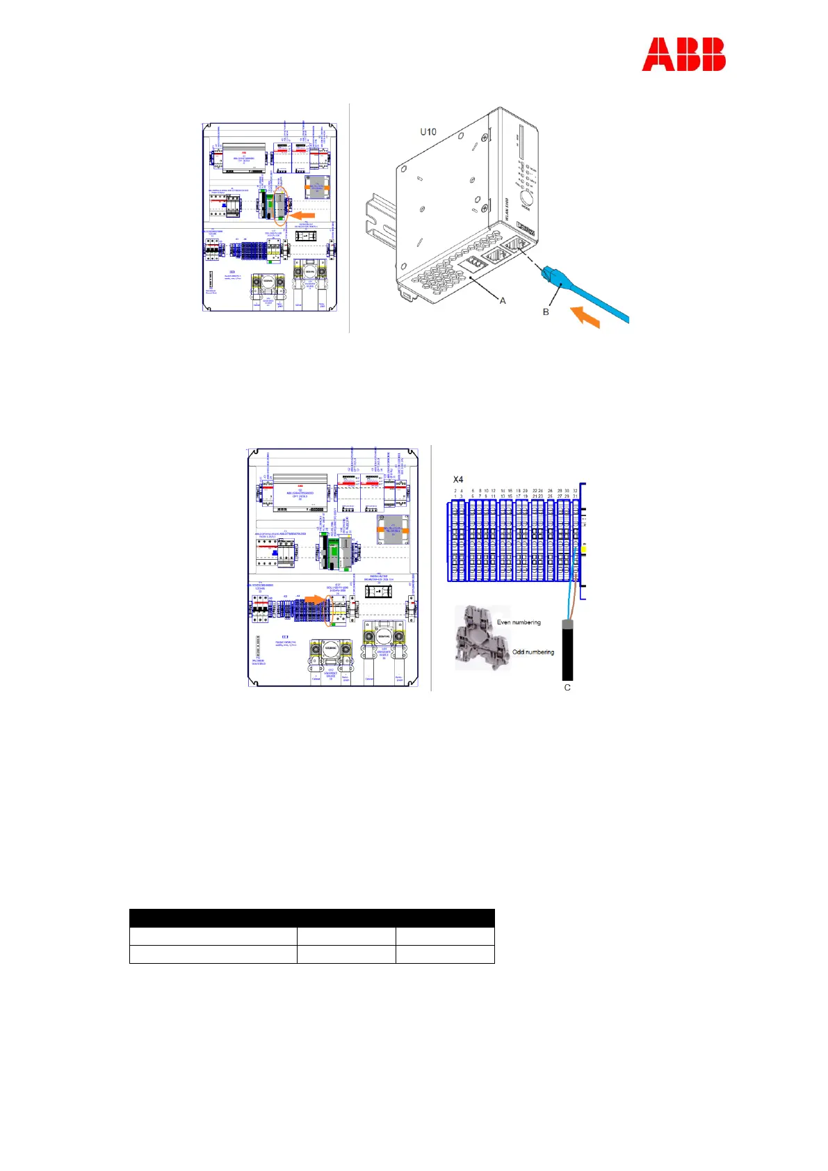
3. Route the RFID Ethernet cable through gland #5 to module U10 (A).
4. Insert the RJ45 connector (B) of the Ethernet cable into the Ethernet port X2 of module
U10 (A)
5. Tighten the nut of the gland to secure the RFID Ethernet cable.
6. Route the RFID Power cable (C) through gland #10 to connector block X4, with sufficient
cable length (do not make the cable routing too tight, or too loose).
7. Tighten the nut of the gland to secure the RFID Power cable.
8. Strip the insulation from the cable.
9. Strip 0.43 Inch of the insulation from the ends of only the Brown and Blue wire!
10. Crimp a ferrule onto the end of the Brown and Blue wire.
11. Cut the other wires, except the Brown and Blue wire, at the end of the striped insulation
of the cable.
12. Loosen the connector screws.
13. Insert the wires into the correct connectors, see table below:
14. Tighten the connector screw.