HVC 450 kW E-Bus Charger Installation Guide
Revision: 1.2 COMPANY CONFIDENTIAL
Date released: 16-08-2018 Page 94 of 128
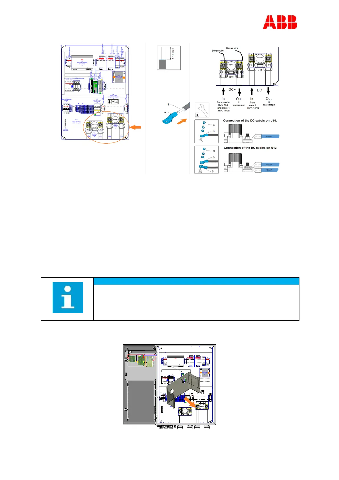
4. Loosen and remove the cable gland’s (#14 - #18 and #20) nuts, including the cover caps
inside the gland, for the DC+ power cables.
5. Slide the cable gland’s nuts over the DC power cables.
6. Strip 1.18 Inch of the insulation from the ends of the wires (B).
7. Insert the DC+ power cables into the right cable gland (#14 - #18 and #20, see picture
above and section Gland layout of the ACS Control Module on Page 92).
8. Attach cable lug (A) at the end of the wires.
9. Remove the nuts and washers (C) from the bolts of the DC contactor connectors.
10. If present: remove the sense wires from the bolts of the DC contactor connectors.
11. Insert the wires (B) onto the correct bolts of the DC contactor connectors, see picture
above for the correct connection.
12. Insert the sense wires back onto the bolts of the DC contactor connectors.
Make sure that the sense wires are placed back on the DC contactor
connectors. If this is not the case, then the system will not function.
13. Tighten the nuts (C) with a tightening torque of 22.13 ft-lb.