Do you have a question about the ABB PST Series and is the answer not in the manual?
Instructions for safe installation and manual accessibility.
Explains caution, warning, and information symbols used in the manual.
Lists available documentation for the softstarter.
Describes the content and purpose of this manual.
Identifies the target personnel for this manual.
Lists the content of each chapter in the manual.
Provides information on document revisions and updates.
Defines common acronyms and abbreviations used in the manual.
Instructions for connecting the softstarter to the system.
Steps for configuring the softstarter for operation.
Procedure for starting the motor using the softstarter.
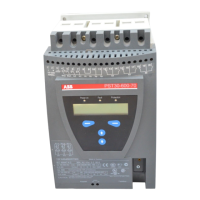
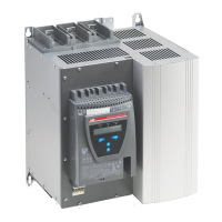
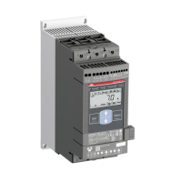
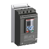
General description of the PST softstarter and its capabilities.
Details on integrated protection, warning, and fault functions.
Identifies terminal markings, connections, and product labels.
Explains the coding system for softstarter model identification.
Details on operating conditions, altitude, and pollution degree.
Lists technical specifications like degree of protection and EMC.
Provides detailed technical data for the softstarter.
Presents electrical and performance data for different softstarter models.
Provides dimensional drawings for PST30...72 softstarters.
Procedure for inspecting the softstarter upon receipt.
Guidelines for storing the softstarter before installation.
General mounting instructions for the softstarter.
Advice on safely handling and mounting the softstarter.
Specifies requirements for mounting, including environmental factors.
Defines required clearances for proper cooling and installation.
Recommends minimum enclosure dimensions and fan capacities.
Introduction to electrical connections and communication devices.
Details on connecting the main circuit and softstarter terminals.
Explains how to connect the softstarter in Line and Inside Delta configurations.
Instructions for connecting an external by-pass contactor.
Details on connecting supply voltage and control circuits.
Wiring for start/stop circuits using internal control voltage.
How to connect and configure programmable inputs In0 and In1.
Wiring for programmable output relay K4.
Connecting the PTC input for motor protection.
Connecting optional communication devices like fieldbus.
Introduction to the HMI functions and capabilities.
Details the components of the HMI: LEDs, LCD, and keys.
Information on setting and managing the keypad password.
Instructions on how to lock and unlock the keypad.
Visual representation of the HMI menu structure.
Describes information and navigation at the top level menu.
Details the types of settings available in the settings menu.
How to use the local control menu for start/stop and jog functions.
Procedure for starting and stopping the motor via the keypad.
Overview of how settings can be configured via keypad or fieldbus.
Table showing which settings are available in different menus.
Describes information and navigation at the top level menu.
Guides through setting predefined parameters for specific applications.
Covers common start/stop parameters for basic setup.
Advanced settings grouped by function, e.g., protection, warnings.
Configuration of various motor protection functions.
Configuration of warning functions for current and overload conditions.
Configuration of fault types and their operational responses.
Setting functions for programmable inputs In0 and In1.
Configuring programmable output relays K4, K5, and K6.
Configuration of fieldbus communication, type, and address.
Setting up sequential motor starts with different parameter sets.
Introduction to fieldbus communication interface and protocols.
Lists accessories needed for connecting to a fieldbus system.
Details on the AS-I protocol and its setup parameters.
Details on the DeviceNet protocol and its setup parameters.
Explains diagnostic messages, error codes, and parameter numbers.
Map showing input data allocation in bytes and words.
Map showing output data allocation in bytes and words.
Comprehensive list of parameters, their types, ranges, and units.
Routine checks for ensuring proper operation and longevity.
Setting the rated motor current for the softstarter.
Configuring the ramp time for motor start.
Configuring the ramp time for motor stop.
Limiting the starting current to protect the motor.
Configuring motor overload protection modes.
Defining actions for overload protection (stop, reset).
Defining actions for locked rotor protection (stop, reset).
Defining actions for underload protection (stop, reset).
Defining actions for phase imbalance protection (stop, reset).
Activating and configuring phase reversal protection.
Activating and configuring PTC protection.
Defining actions for by-pass fault monitoring.
Configuration of programmable inputs In0 and In1.
Configuration of programmable output relays K4, K5, and K6.
Activating and controlling the softstarter via fieldbus.
Setting up sequential motor starts with different parameter sets.
Selecting the display language for the LCD.
Introduction to troubleshooting guide for softstarter issues.
Lists common problems, causes, and solutions for softstarter operation.
Troubleshooting guide for faults occurring during softstarter startup.
Details on how faults are indicated and their troubleshooting steps.
How protections are indicated and troubleshooting steps for each.
Electrical circuit diagram for PST30 to PST300 models.
Electrical circuit diagram for PSTB370 to PSTB1050 models.
| Brand | ABB |
|---|---|
| Model | PST Series |
| Category | Controller |
| Language | English |