15
1SFC132003M0201
4XLFNVWDUW
&KDSWHU
&KDSWHU4XLFNVWDUW
This chapter is a short guide to how to connect, do the
configuration and start the softstarter in the easiest way.
:DUQLQJ
0RXQWLQJHOHFWULFDOFRQQHFWLRQDQGVHWWLQJVRIWKH
VRIWVWDUWHUVKDOOEHPDGHLQDFFRUGDQFHZLWKH[LVWLQJ
ODZVDQGUHJXODWLRQVDQGEHSHUIRUPHGE\DXWKRULVHG
SHUVRQQHO
'RQRWFKDQJHDQ\SDUDPHWHUVLQWKH6HUYLFH6HWWLQJV
PHQX
&RQQHFWLRQ
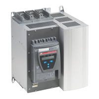
1. Mount the softstarter according to Chapter 4 “Mount-
ing” .
2. Be aware of the ambient temperature.
Derating is required above 40
°C (104 °F).
3. Connect the main circuit: terminals 1L1 - 3L2 - 5L3 to
the line side and terminals 2T1 - 4T2 - 6T3 to the motor
side.
4. Connect the supply voltage: terminal 1 and 2
(100-250V 50/60Hz).
5. Connect the functional ground: terminal 3.
7KHZLUHVKDOOEHDVVKRUWDVSRVVLEOHDQGEHFRQQHFWHGWR
WKHPRXQWLQJSODWH
7KHPRXQWLQJSODWHVKRXOGDOVREH
HDUWKHG
6. Connect the start/stop circuits: terminal 4, 5, 8, 9 and
10 according to the diagram.
7. Check that the main and supply voltage corresponds to
the softstarter ratings.
8. Switch on the supply voltage.
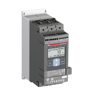
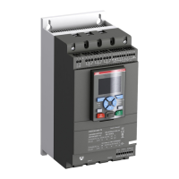
9. The green "Power on" LED is on and the LCD shall
appear as in figure 3.
Power on ProtectionFault
1
2
3
4
)LJXUH
1 Status indication LEDs
2 LCD display
3 Selection keys for selecting, changing and
storing parameters
4 Navigation keys for navigating in the
menus
Arrows shown in the display indicates that
the value/menu is possible to change or
scroll
7 +#
/GPW
L1
L2
L3
N
KM1
1L1 3L2 5L3
2T1 4T2 6T3 6 7 8 9
12 13 14 15 16 17 18 19 20
U
V
W
12 3 4 5
10
45
10
11
M
3
Stop Start
Stop
Start
)LJXUH 6WDQGDUGFRQQHFWLRQ367
Power on ProtectionFault
)LJXUH 7RSOHYHO
7 +#
/GPW
 Loading...