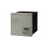
Auxiliary unit for REG216/316*4 for 100%
stator and rotor earth fault protection
ABB Switzerland Ltd
Utility Automation
REX010/011
1MRB520123-Ben
Page 2
Design General
The earth fault protection is based on the in-
jection of a coded signal. The resulting offset
voltage is utilized to calculate the earth resis-
tance (R
f
).
The injection signal is produced in the injec-
tion unit REX010 and applied to the genera-
tor through the transformer unit REX011. For
the coupling to the protected unit resistors
(R
E,
R
P
) are used. For the rotor earth fault
protection two capacitors are required in
addition.
The measurement signals for earth fault pro-
tection are processed by the REG216 or the
REG316*4 respectively.
The equipment described protects 100% of
the generator stator winding. Two indepen-
dent protection functions are applied: one for
95% and one, using a different algorithm, for
100% of the stator winding. The 100% func-
tion is calculating the earth resistance and the
95% function is measuring the neutral voltage
displacement of the generator.
a) The 100% function protects 35% of the
stator windings from the neutral point
for R
f = 0
and I
0max
= 15 A
b) The 95% function (U>) protects 95% of
the generator stator winding from the
terminals. This results in an overlap
(redundancy) of the two protection func-
tions as seen in Fig. 1.
The 100% function increases in sensitivity
with increasing earth fault resistance and
decreasing earth fault current.
Fig. 1
At standstill the full stator winding (100%) is
protected by the 100% function as seen in
Fig. 2. At the same time the entire excitation
winding is protected for earth faults. Because
of the excellent rejection of external interfer-
ences, the REX010/011 can be applied to all
types of excitation systems including thyris-
tor type.
Fig. 2
Hardware The protection equipment consists of the fol-
lowing units (Figures 4 – 8):
REG216/316*4: Numerical generator protection
REX010: Injection unit
REX011: Injection transformer unit
with auxiliary contactor
In addition the following components are
required:
- Earthing resistors in the generator neu-
tral point (R
ES
, R
PS
) and in the excita-
tion circuit (R
Er
, R
Pr
)
- Coupling capacitors in the excitation
circuit of the rotor
- Voltage transformers
The injection unit (REX010) together with
the injection transformer (REX011) produces
three coded square wave signals (Uis, Uir,
Ui) with a frequency f
N
/4. These square wave
signals are injected into the protected object
via the coupling components. The three
square waves have different amplitudes: Uis
(Injection signal for the stator), Uir (Injection
signal for the rotor) and Ui (reference signal
for the REG216/316*4). The injection unit
REX010 is connected to the station battery
and the injection signal voltage is generated
either by the battery or by an internal DC/DC
converter.
95% Stator earth fault protection
100%
function Rf = 0
Ω
Stator earth fault
Rf > 0
Ω
eutral point
Winding
Running machine
100% Stator earth fault function

 Loading...