6146/6156 DC Voltage/Current Generators Operation Manual
4.1.2 Remote Sensing (2-Wire or 4-Wire Connection)
4-2
• When using within the specified accuracy
6146:
(Lead resistance × output current) < 100 μV→ 2-wire connection
(Lead resistance × output current) ≥ 100 μV→ 4-wire connection
6156:
(Lead resistance × output current) < 10 μV→ 2-wire connection
(Lead resistance × output current) ≥ 10 μV→ 4-wire connection
The lead resistance of the provided cable A01044 is approx 100 mΩ. When this cable is used and the
following total output current is obtained from the above calculation, use 4-wire connection.
6146: 1 mA or more
6156: 100 μA or more
• When allowing the error voltage (ev).
(Lead resistance × output current) < ev→ 2-wire connection
(Lead resistance × output current) ≥ ev→ 4-wire connection
When the provided cable A01044 is used and the error voltage of 10 mV is allowed, the 2-wire con-
nection can be used up to 100 mA.
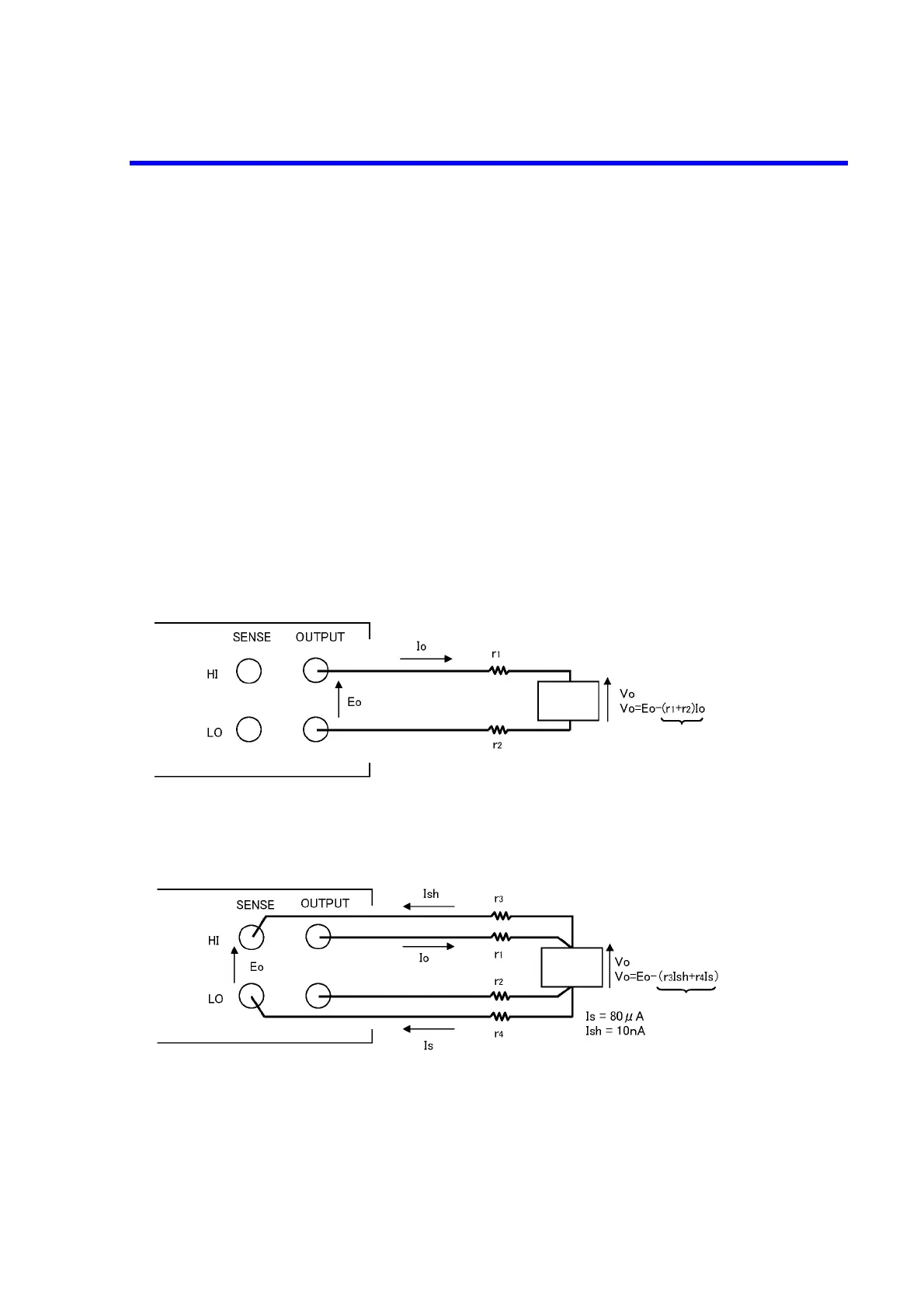
Figure 4-2 2-Wire and 4-Wire Connections
An error may occur due to r1 and r2 voltage drop.
(b) 4-wire connection and error due to lead resistance
r1, r2: lead resistance
Eo: setting voltage
Io: load current
Vo: load voltage
r1, r2, r3, r4: lead resistance
Eo: setting voltage
Io: load current
Is: voltage sensing current
Ish: Hi-side voltage sensing current
Vo: load voltage
Load
Error
Load
Error
(a) 2-wire connection and error due to lead resistance
 Loading...