6146/6156 DC Voltage/Current Generators Operation Manual
4.2.9 External Control Signals
4-23
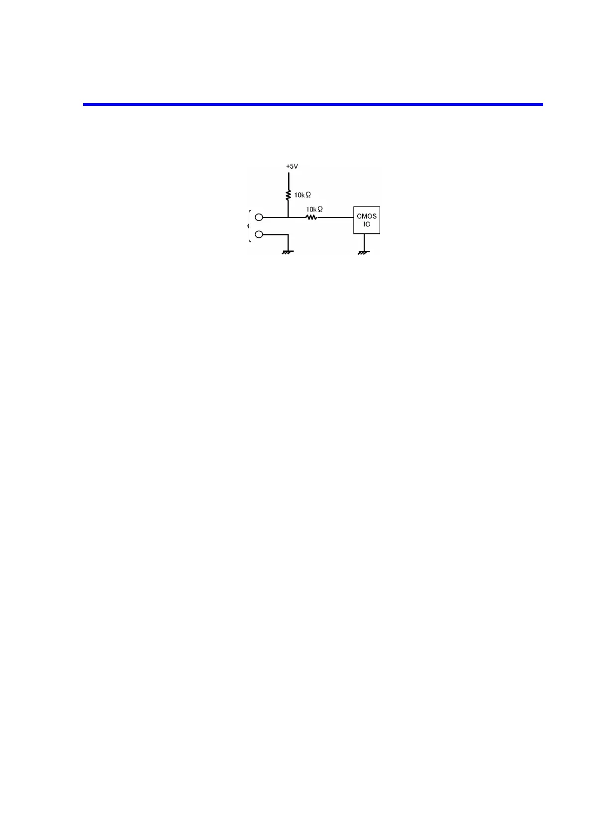
Figure 4-10 TRIGGER IN Input Circuit
4.2.9.1.1 Restrictions on Using External Trigger
As slave in the synchronized operation, the TRIGGER IN signal controls the source timing to synchronize
with the external devices.
Confirm the following restrictions before inputting the external trigger to prevent any malfunctions.
1. Do not input the TRIGGER IN signal in Standby status, when switching between Operate, Suspend,
and Standby, or when changing the range.
2. Ensure that the TRIGGER IN signal, the trigger from the TRG key, and Remote trigger (*TRG) do
not overlap.
3. Allow the 6146/6156 at least 10 ms after completion of the previous sweep to input the TRIGGER
IN signal for sweep start.
4. Do not use the TRIGGER IN signal when selecting the BCD interface.
5. Set the input interval of the external trigger to at least 10 ms.
4.2.9.2 READY OUT/SYNC OUT
For READY OUT and SYNC OUT, the same terminal is used by switching.
Set selecting MENU, E.SYG and READY in that order.
There are two settings; READY and SYNC.
The following shows the specifications of the READY OUT/SYNC OUT signal.
High: +2.7 V to +5.25 V 100 μA max.
Low: 0 V to +0.6 V -1 mA max.
Pulse width: Approx. 10 ms (negative pulse)
Used connector: BNC
READY OUT/SYNC OUT output circuit: See the following figure.
TRIGGER IN
signal input
 Loading...