6146/6156 DC Voltage/Current Generators Operation Manual
4.2.9 External Control Signals
4-22
4.2.9.1 TRIGGER IN
The TRIGGER IN signal triggers the 6146/6156 from the external device.
The following table shows the source modes and their operations.
For the operation timing of each mode, refer to Section 4.2.1 through Section 4.2.4.
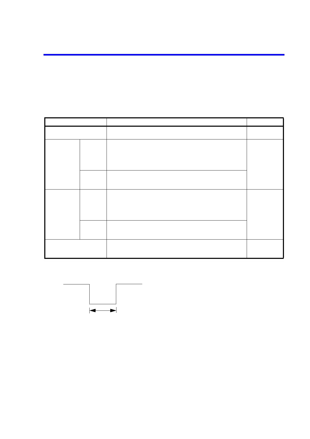
TRIGGER IN signal: TTL negative pulse
High: +2.4 V to +5.25 V
Low: 0 V to +0.4 V
Used connector: BNC
TRIGGER IN input circuit: See the following figure.
Table 4-9 TRIGGER IN Operations
Source mode Operation by TRIGGER IN signal Remarks
DC source mode • During continuous operation, stops the operation at the falling
edge.
Sweep source
mode
Single/
Repeat
• When sweep operation is stopped, starts the operation at the fall-
ing edge.
• During sweep operation, pauses the operation at the falling edge.
• When sweep operation is paused, resumes the operation at the
falling edge.
Refer to Section
2.3.2, "Sweep
Source Mode."
Hold • When sweep operation is stopped, starts the operation at the fall-
ing edge.
• During sweep operation, proceeds one step at the falling edge.
Memory recall
mode
Single/
Repeat
• When scan operation is stopped, starts the operation at the falling
edge.
• During scan operation, pauses the operation at the falling edge.
• When scan operation is paused, resumes the operation at the fall-
ing edge.
Refer to Section
2.3.1, "Memory
Recall Mode."
Hold • When scan operation is stopped, starts the operation at the falling
edge.
• During scan operation, proceeds one step at the falling edge.
Continuous function of the
DC source mode
• During continuous operation, stops the operation at the falling
edge.
Refer to Section
2.2.7, "Continu-
ous Function."
2 μs or more
+2.4 V to +5.25 V (or Open)
0 V to +0.4 V (or short-circuited to GND)
 Loading...