22
Barcode Port Connections Advanced
™
Osmometer 3250/Cryoscope 4250 Service Manual
Head Sensor Board (3D3380) Description:
This board provides two optical sensors that interface to a PLD on the main board. These two
sensors detect the head-up and head-down conditions.
Keypad Transition Board (FLO520) Description: This board provides the interface to the
keypad along with pull-up resistors for the keypad LEDs.
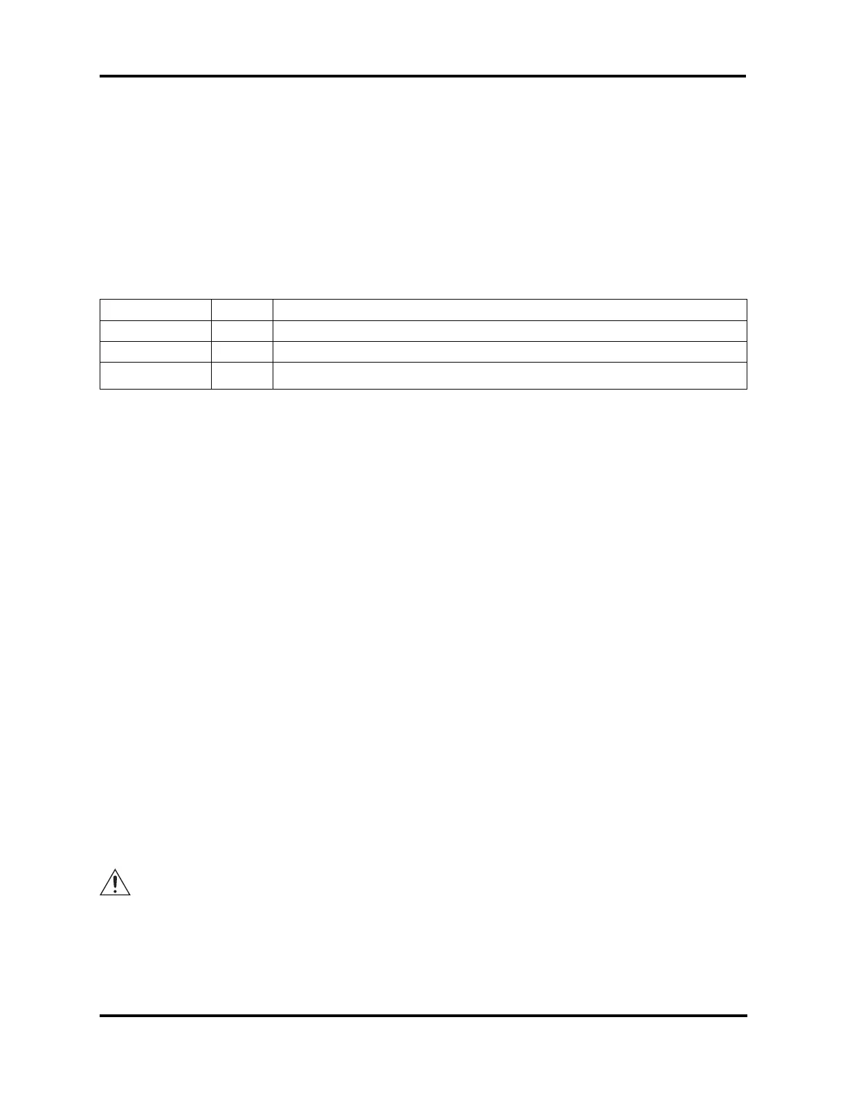
Barcode Port: A D-type, 15-pin barcode port is provided in the back of the instrument for
connecting and providing power to such a device. For proper operation, the barcode port
requires a 1200 bps, RS-232 signal providing asynchronous serial data containing 1 start bit, 8
data bits, 1 stop bit, and no parity.
Signal Pin Direction
+5V DC 1 to reader
receive data 10 from reader
gnd/earth 9 common
Barcode Port Connections
A suitable barcode scanner is available from Advanced Instruments. To interface with the
instrument, the barcode scanner must be programmed as follows, referring to the scanner
users guide.
• 1200 bps
• CR suffix
• disable beep after good decode
• triggerless trigger mode (optional)
Internal Printer, Serial Suffix A - C: The internal printer assembly (325400) consists of the
sheet metal mounting bracket, thermal print head (FL0403), thermal printer PCB (FL0402),
and thermal printer PC board assembly (PCB400). All of this is connected to the application
board (PCB605) via cable (M20465).
Note The internal printer may be powered by +5 VDC (red/orange wire) or +12 VDC (violet
wire). Consult system schematics for proper service.
Internal Printer, Serial D and Higher: The internal printer assembly (325420) consists of the
sheet metal mounting bracket, thermal print head (325404), main control board (325421),
printer interface board (PCB402), and the control cable (325419). All of this is connected to
the application board (PCB605) via cable (325415), and on some models via cable (325033).
The printer interface board (PCB402) contains the power circuit converting +12 VDC into
+5 VDC, a feed/self-test switch (S1), and some diagnostic LEDs. If the self-test switch is
depressed as instrument power is applied, the printer will enter self-test mode and print out
settings and a test character set. The LEDs indicate the operation of the paper-out detector
(D1 yellow) and the door/platen-closed detector (D2 red).
Power connection to J1 should not be reconnected with instrument power on, or
damage to the instrument may result.
The printer control board (325421) translates the data from the application board (PDCB605)
into control signals for the print head thermal elements and drive motor (325404). This
board also contains a factory-set configuration DIP switch (DS1) and jumper (JP1).