PCB522 Transistor Replacement Instruction
35050 to PCB522R Substitution
(Models 4D3, 3D3, 3250*, 4C3, 3900, and 4250*)
*Not for use on Models 3250/4250 with
serial suffix D and higher.
Reference: Use this instruction to install
part PCB522R, which is intend-
ed as a direct replacement for
part 35050 metal can Darlington
transistor used on some of the
above models.
Materials Included:
1 - PCB520 assembly
2 - H50606, #6x3/8 Sems
2 - H50608, #6x1/2 Sems
2 - H63093, #6 large flat washers
2 - 90049, Hex swage standoffs
2 - 91038, ¼” plastic hole plugs
Tools Needed: Wire cutters, wire strippers,
small flat-bladed screwdriver,
medium Phillips screwdriver.
Warning-Hazardous Voltage
Warning-Internal components may
be damaged by static electricity.
4D3, 3D3, 3250, and 4250 Instruction:
1. Turn off the instrument power and dis-
connect the power cord.
2. Remove the intrument cover.
3. Locate transistor Q2B on left-rear of the
chassis. Q2B is the transistor nearest to
the bottom of the rear panel.
4. If your instrument already has PCB522 in
this location, remove the old PCB and
skip to step 11.
For additional information or technical assistance,
please contact Advanced Instruments Hot-Line
®
Service Center (U.S. 1-800-225-4034, outside North
America +US 1-781-320-9000).
5. Remove the screws securing the protec-
tive black plastic cap on the outside rear
of the instrument.
6. Remove the old transistor and insulating
materials by gently prying with a flat-
bladed screwdriver.
7. Remove the transistor socket Q2B from
the rear panel and clear the mounting
holes of any remaining hardware.
8. Cut transistor socket Q2B from harness
M20150.
9. Strip wire insulation ¼” on four (4) wires
formerly soldered to the transistor socket.
Twist the stripped ends to prevent fraying.
10. Install the hex standoffs to PCB522 using
#6x3/8 screws, with the flat end of the
standoff against the board.
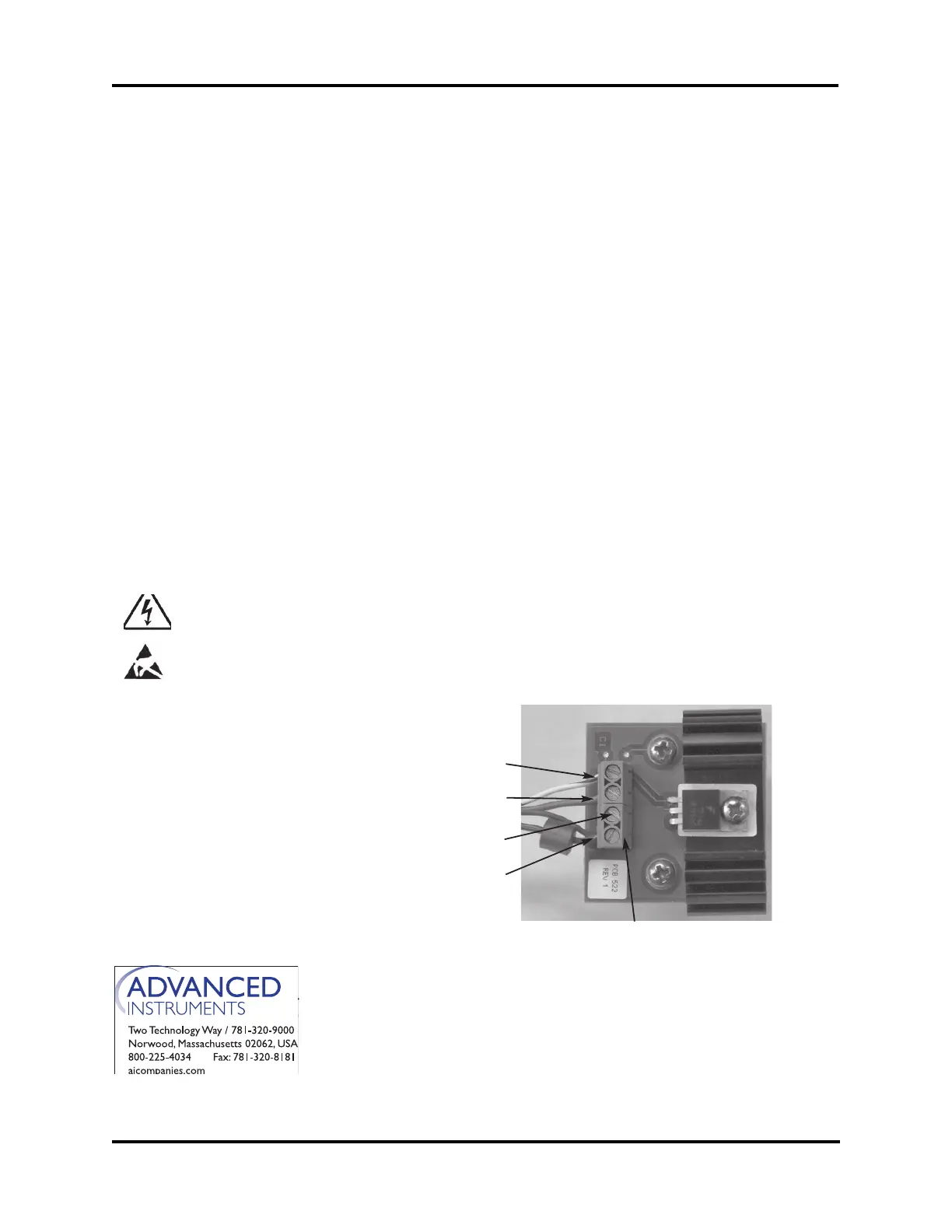
11. Connect white/blue wire to terminal 1
(A).
12. Connect violet wire to terminal 2 (B).
13. Terminal 3 (C) is unused.
PCP522R Rev3
(4D35/4C35/3255/3905 Service Manual)
Page 1 of 3
A
B
C
D
E