325P620 Rev7
(3255 Service Manual)
Page 2 of 4
3. Remove the replacement board set from
its anti-static bag, taking care not to dis-
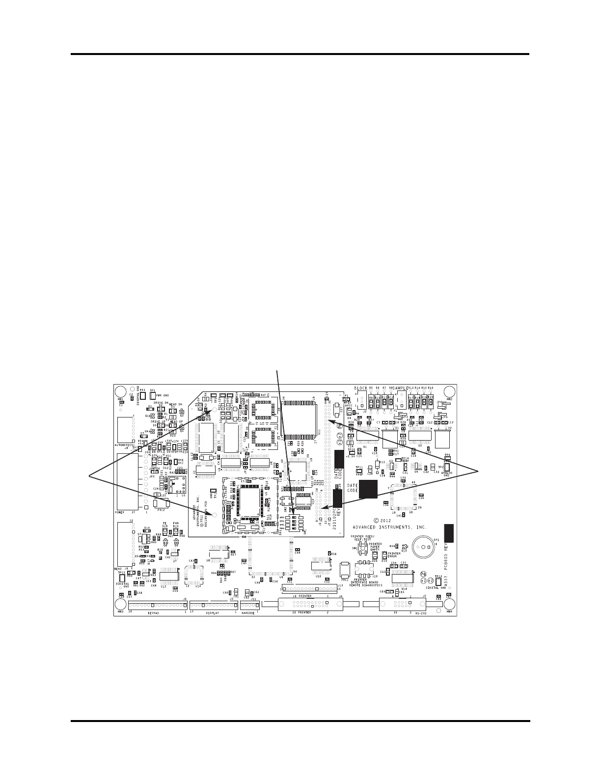
turb the options/configuration switch
SW1 (A), located on the processor board
(smaller of two).
4. Press the new board set onto the four
snap-on standoffs so that the words
“Advanced Instruments, Inc.” are located
in the upper left corner. Reinstall two
screws, if applicable.
5. Reconnect all wiring connections and
proceed to the REASSEMBLE AND
CHECKOUT instruction, below.
Application Board (larger of two)
Replacement:
1. Remove the wiring connectors from the
application board (larger of two).
2. Gently pry the board set off the four
snap-on standoffs.
Note: Some instruments may require two
screws be removed prior to removing
the board set.
3. Remove the processor board (smaller of
two) by first releasing the two plastic
standoffs at locations E3 and E4 (B), taking
care not to disturb the options/configuration
switch SW1 (A). Next, gently pry the
processor board off its J1 and J2 connectors
(C) by rocking it from top to bottom.
4. Remove the replacement application
board from its anti-static bag.
5. Install the processor board onto the new
application board by reversing step 3,
being careful to firmly seat the J1 and J2
connections and aligning pins to sockets.
6. Press the new board set onto the four
snap-on standoffs so that the words
“Advanced Instruments, Inc.” are located
Two-Board Set
A
C
B