41
Performing FLASH firmware update Troubleshooting
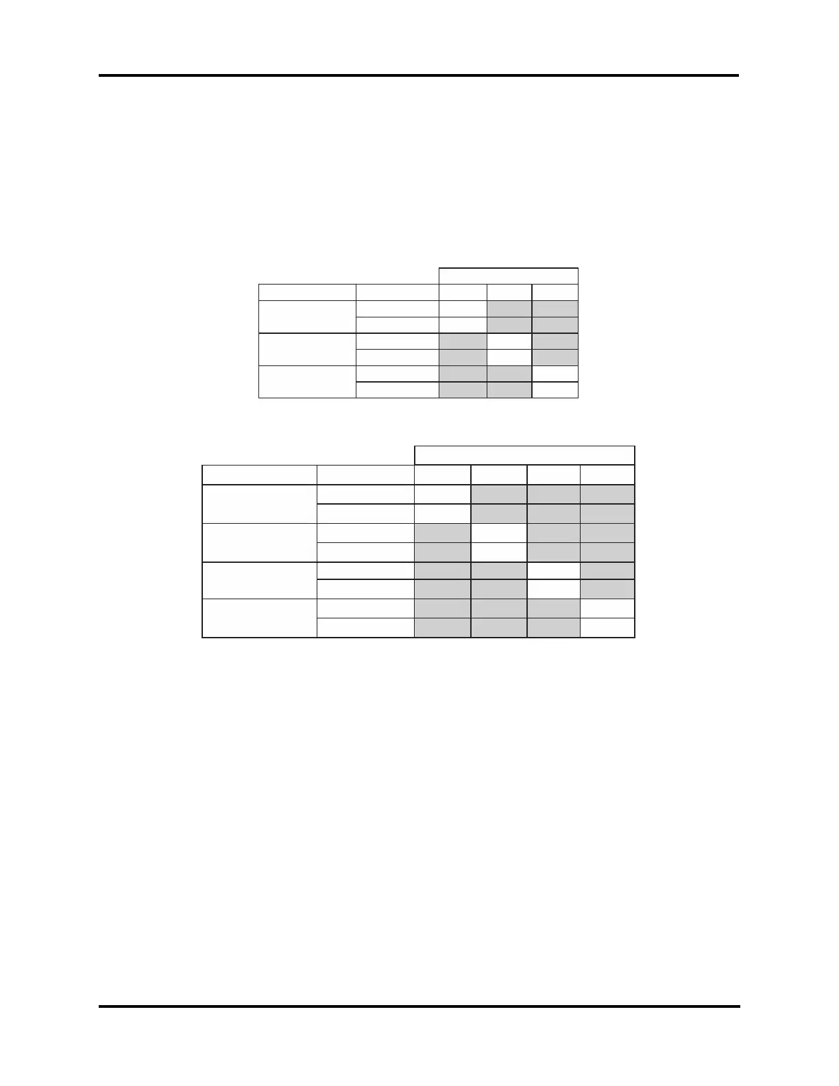
Option Switch Settings
The processor board is equipped with a dip switch. Each switch position and combination of
positions can be used to configure different programming options, such as the programming
option listed above for Flash update mode.
If your settings should accidentally get changed, or your replacement processor board is
shipped from the factory with the incorrect settings for your product, the following tables
detail the appropriate switch positions for restoring your instrument to proper operation.
Option Switch Setup Table - 3-Position Switch
Switch Function
Selections
1 2 3
#1 Selects Instrument
3250 ON
4250 OFF
#2 Selects Printer
Citizen ON
Seiko OFF
#3 Selects Mode
Program ON
Normal Operation OFF
SW1
Option Switch Setup Table - 4-Position Switch
Switch Function
Selections
1 2 3 4
#1 Selects Mode
(“PROG”)
Flash Boot
ON
Normal Operation OFF
#2 Selects Printer
(“OPT1”)
Citizen
ON
Seiko OFF
#3 Selects Instrument
(“OPT2”)
3250
ON
3250 OFF
#4 Not in Use
(“OPT3”)
N/A ON
N/A OFF
SW1