Power Supply Assembly Replacement
4D3950/325950R
For additional information or technical assistance,
please contact Advanced Instruments Hot-Line
®
Service Center (U.S. 1-800-225-4034, outside
North America +US 1-781-320-9000).
325P950 Rev2
(4D35/3255/MK05 Service Manual)
Page 1 of 3
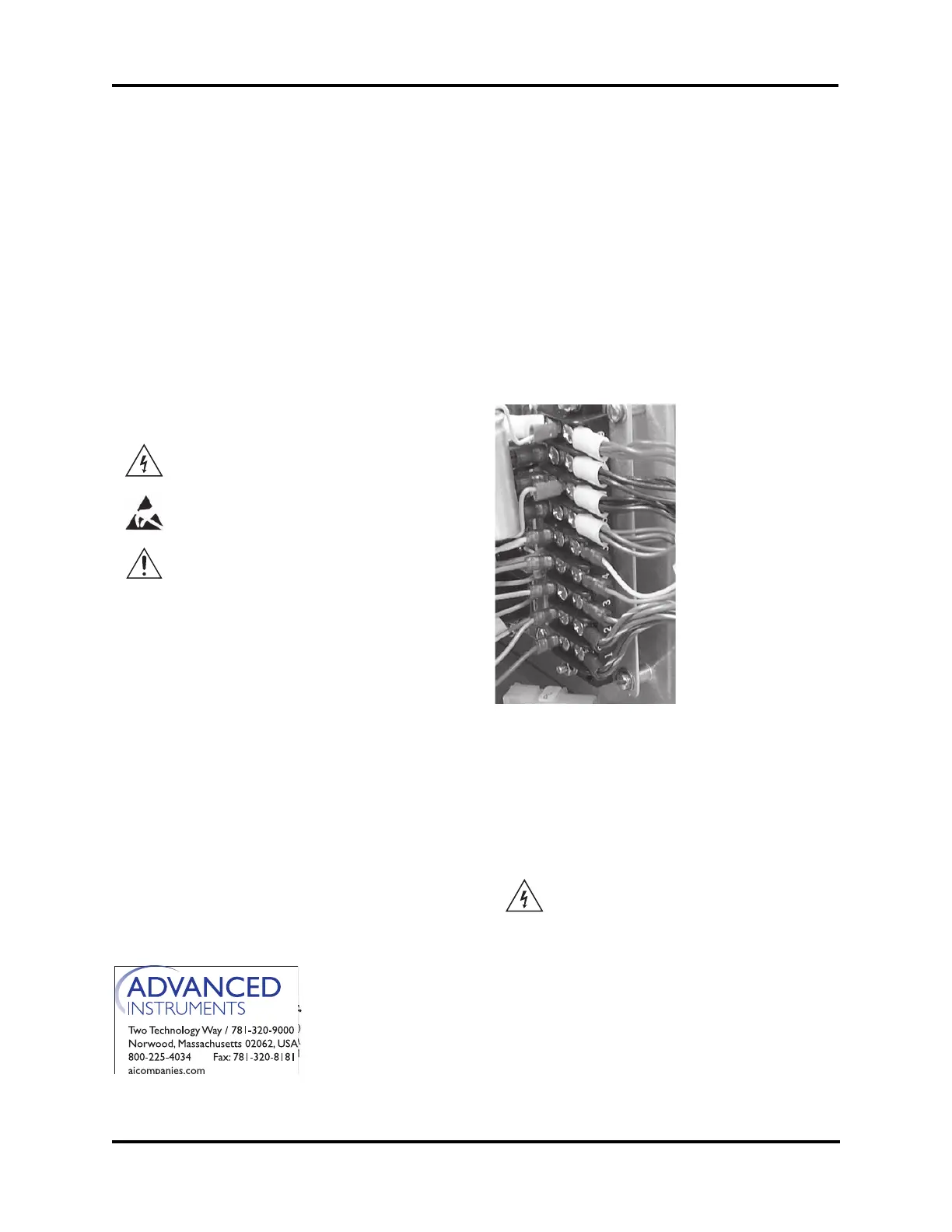
5. Identify and disconnect the wiring har-
ness connections from the power supply
terminal strip. Note the wire colors and
the corresponding connectors.
6. Remove the four screws and nylon wash-
ers from the power supply board.
7. Replace the old power supply with the
new one and reassemble by reversing
steps 1-6.
Reference: Use this instruction with replace-
ment part 4D3950 or 325950R.
Use 4D3950 with Models 3250/4250 Serial
Suffix A - C, 3D3, 4D3, Mark 2, or Mark 3.
Use 325950R with Models 3250/4250 Serial
Suffix D or higher.
Tools Needed: Phillips screwdriver, flat-
bladed screwdriver, static
grounding (earthing) wrist
strap (included).
Warning-Hazardous Voltage
Warning-Internal components may
be damaged by static electricity.
CAUTION: Improper connections
may cause damage to the instrument.
4D3950 Instruction:
1. Turn off the power and unplug the instru-
ment.
2. Remove the screws securing the head
cover, and remove the cover.
3. Remove the screws securing the instru-
ment cover, and remove the cover.
4. The power supply is mounted on the ver-
tical mounting panel behind the main
printed circuit boards. Remove the two
rear screws and the two bottom screws
securing the power supply mounting
panel and lift the entire assembly out far
enough to access the power supply.
red
black
black
violet
yellow
orange
green/yellow
blue/white
brown/white
325950R Instruction:
1. Turn off the power and unplug the instru-
ment.
CAUTION: IT IS CRITICAL THAT THE
INSTRUMENT BE UNPOW-
ERED THROUGHOUT THIS
REPLACEMENT PROCE-
DURE. ALWAYS UNPLUG
THE INSTRUMENT FOR
PERSONAL PROTECTION