Reference: Use this instruction with replace-
ment part 3D3109.
Tools Needed: Phillips screwdriver, flat-
bladed screwdriver.
Warning-Hazardous Voltage
Warning-Internal components may
be damaged by static electricity.
CAUTION: Improper connections
may cause damage to the instrument.
Note: Serial Suffix A - C, only.
Instruction:
1. Turn off the power and unplug the instru-
ment.
2. Remove the screws securing the head
cover, and remove the cover.
3. Remove the screws securing the instru-
ment cover, and remove the cover.
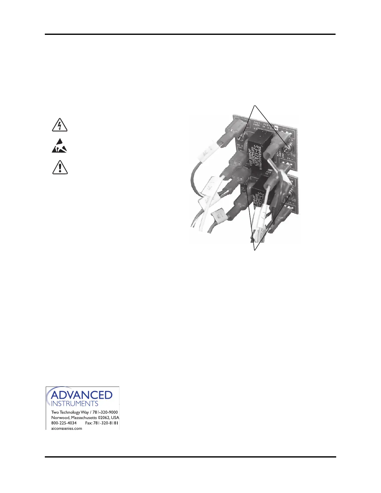
4. Locate the Head Up/Head Down Relay
on the inside rear wall (Fig. 1). Note the
wire colors and the corresponding con-
nectors, and then remove the connectors.
5. Remove the screws (Fig. 1A) from the
relay and remove the old relay.
6. Mount the PCB502 relay board (Fig. 2)
onto the standoff studs and secure the
board.
Head Up Relay or Head Down Relay Replacement
3D3109
For additional information or technical assistance,
please contact Advanced Instruments Hot-Line
®
Service Center (U.S. 1-800-225-4034, outside
North America +US 1-781-320-9000).
325P109 Rev2
(3255 Service Manual)
Page 1 of 2
Head Up Relay
Head Down Relay
A
A
Blue
Orange
Blue
White
Brown
Yellow
Brown
Gray
Figure 1
Note: As of instrument serial suffix C, the
single relay board PCB500 has been
replaced by a dual relay board
PCB502.