33
Head Sensor Adjustment Troubleshooting
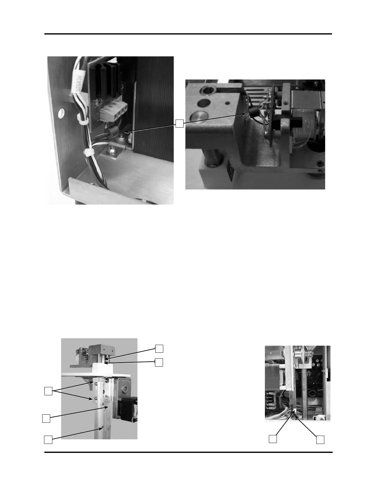
Installation Option B
B
Note For installation option B, one ferrite bead [B] is located on the light blue wire running
between PCB522 pin 4 and J3B. The second ferrite bead [B] is located on the white
wire exiting the head shaft and attached to TR2 on the head transition board.
Head Sensor Adjustment
1. Turn off the power and unplug the instrument. Remove the instrument cover and the
head cover. Place an empty sample tube in the sample well.
2. Manually push the head all the way down until the head stop screw [C] meets the base of
the deck [D].
3. The head position sensors are located on the head sensor board. To adjust the head
sensor position, use an Allen wrench and loosen the two bracket screws [E], and move
the board [F] and bracket [G] either up or down until the head sensor flag [H] is in the
middle of the head down sensor [I].
Note To facilitate access to the two bracket screws [E], loosen and move the printer
bracket assembly.
C
D
E
F
G
H
I