69
Heat Transfer Fluid Pump Assembly Replacement 4D390 Replacement Instructions
4DP690 Rev3
(4D35/3255/MK05 Service Manual)
Page 3 of 7
3. Drain the system:
a. Remove the heat transfer fluid bottle
and empty the contents.
b. Replace the empty bottle and insert
the tubes.
c. Press and release gently on the pump
(A) at the rear of the cooling assem-
bly (see Figure 2). Continue until all
liquid has been expelled.
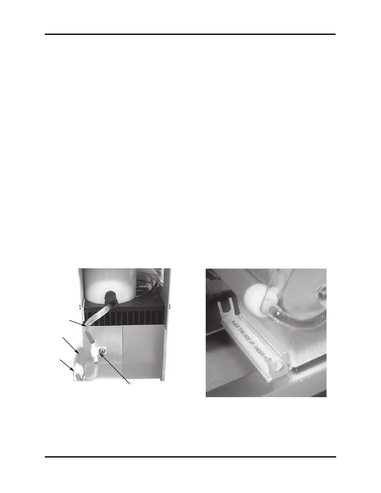
4. If present, remove the screw holding the
cable clamp (B) to the cooling system
shroud (see Figure 2). Firmly gripping
the cooling system inlet tube (C), remove
the check valve, disconnecting the pump
from the cooling assembly.
5. Remove the pump (A) from the bracket
(D).
6. Feed the fluid filter end of the pump
assembly up and around the cooling sys-
tem support brackets, and remove the
pump assembly.
7. Replace the old assembly with the new
one.
a. If the instrument is a 3D3 or Mark
3 osmometer and the Spacer Strip is
not present, remove the green liner
and install the Spacer Strip as shown
in Figure 3. This will ensure that the
proper amount of heat transfer liquid
is pumped during each cycle.
b. Proceed with the installation of the
new pump assembly by reversing
steps 1-4, making sure to use the
cable clamp already installed on the
new pump assembly. Note the orien-
tation of the cable clamp (see Figure
4).
c. Note that just above the heat transfer
fluid bottle, a small priming pump has
been added to assist with priming and
emptying the pump assembly. This
should be positioned as shown in
Figure 6.
d. Make sure that there is no fluid leak-
age from the tubing connections.
Figure 3
C
D
A
B
Figure 2