ARK-6310 User Manual 8
The following procedures are intended to aid in the ARK-6310 system setup and
maintenance. Please also refer to Appendix A, Exploded Diagram, for all the parts
of the ARK-6310.
2.1 Connecting the Power
The ARK-6310 Embedded Systems have built in a power inlet by a 2-pole of Phoenix
connector, that could allow users to connect 14 V
DC
~24 V
DC
input voltage externally.
Please refer to the Figure 2.1 and Table 2.1.
Figure 2.1 Power Input Connector located on Front Panel
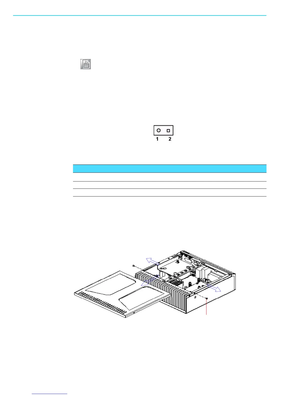
2.2 Removing the Chassis Cover
To remove the top cover of ARK-6310, refer to Figure 2.2 and proceed as follows:
1. Loosen the two screws on the sides near the rear of the chassis.
2. Remove the chassis top cover by gently sliding it backwards.
Figure 2.2 Removing the chassis cover
Note! Use caution when the chassis is open. Be sure to turn off the power,
unplug the power cord and ground yourself by touching the metal chas-
sis before you handle any components inside the machine.
Table 2.1: Power Input connector pin assignments
Pin Signal Name
1 GND
2 +14 ~ 24 V
DC
M3 screws x 2 pieces