15 ARK-6130 User Manual
Chapter 2 System Setup and Maintenance
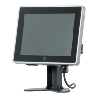
! To remove the DIMM/SODIMM modules, push the two ejector tabs on the slot
outward simultaneously, and then pull out the DIMM/SODIMM module.
2.6 Jumper and Connector List
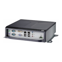
You can configure your board to match the needs of your application by setting jump-
ers. A jumper is the simplest kind of electric switch.
It consists of two metal pins and a small metal clip (often protected by a plastic cover)
that slides over the pins to connect them. To “close” a jumper you connect the pins
with the clip. To “open” a jumper you remove the clip. Sometimes a jumper will have
three pins, labeled 1, 2, and 3. In this case, you would connect either two pins.
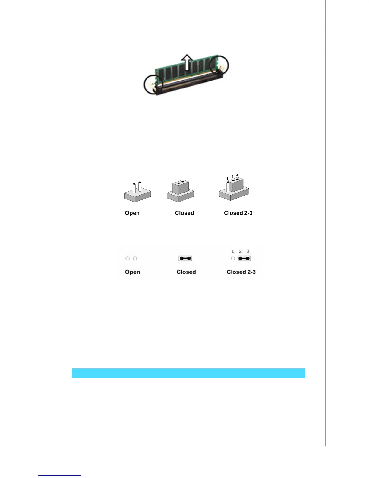
The jumper settings are schematically depicted in this manual as follows:
A pair of needle-nose pliers may be helpful when working with jumpers. Connectors
on the board are linked to external devices such as hard disk drives, a keyboard, or
floppy drives. In addition, the board has a number of jumpers that allow you to config-
ure your system to suit your application. If you have any doubts about the best hard-
ware configuration for your application, contact your local distributor or sales
representative before you make any changes.
2.6.1 ARK-6310 Jumper List
The following tables list the function of each of the system's jumpers and connectors.
Jumpers
Table 2.2: Jumpers
ARK-6310-3M01/02 ARK-6310-6M01 Function
JBAT1 CCMOS1 Clear CMOS
JP1
JP2, JP3
JCOMPWR1 ~4
-
COM1 ~ 4 RI/+5V/+12V Selection
COM1 RS-232/422/485 Selection
- SM_PWRBTN1 ATX (default)/AT Mode Selection