Chapter 4 Angular Measurements
Angular Position Measurements
4-26 Measurements Reference Guide
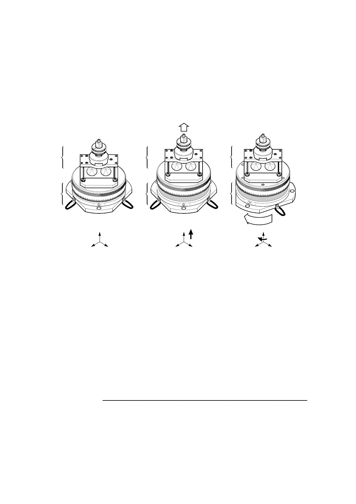
Figure 4-16A. Angular position measurements—principles (Part 1 of 2)
0
10
20
350
30
40
50
60
70
80
90
100
110
340
330
320
0
10
20
350
30
40
50
60
70
80
90
100
110
340
330
320
3
Y
ZX
1
Y
ZX
0
10
20
350
30
40
50
60
70
80
90
100
110
340
330
320
2
Y
ZX
1a
1b
2a
2b
3a
3b
1 Table “neutral” position 2 Table “disengaged” position 3 Table base rotated
1a No force on clutch
For the machine control
program shown in Figure 4-18,
the clutch is depressed 1 mm
from this position. This motion
ensures appropriate
engagement force between the
table’s top and base.
2a Lift top 3 mm to allow base to
rotate. First mm lift returns to
“neutral” position and re-
engages the clutch; remaining
2 mm provides clearance
between table’s top and base,
to allow base to rotate. Set the
machine’s reference point
(relative zero) for this axis after
you have performed this lift.
3a Table top has been disengaged, as
described in 2a.
1b Table top engaged with base 2b Top lifted to allow base to
rotate, as described above.
3b Machine part being calibrated is
rotated, turning the table’s base with it.