Chapter 4 Angular Measurements
Angular Position Measurements
Measurements Reference Guide 4-31
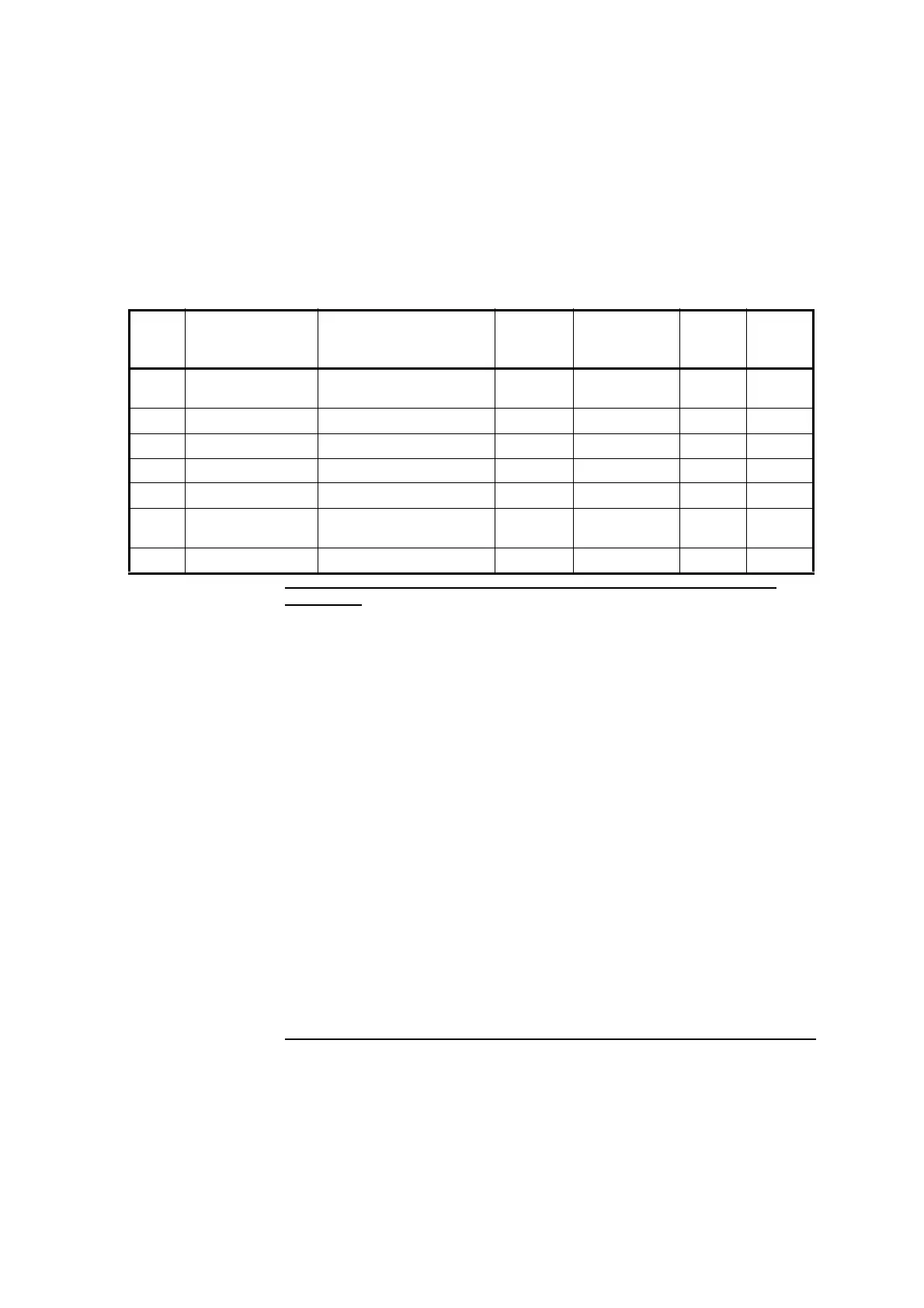
Figure 4-17D. 55290A/B Angular Position Measurements Kit (option 744)—
(Part 4 of 4)
Procedure — summary
The angular position measurement procedure has the major activities
listed below.
1 Program the machine you will be calibrating.
2 Initially set up the computer and laser head.
3 Mount and align the precision index table.
4 Choose and mount the moveable optic.
5 Mount the fixed optic.
6 Align the laser beam to the measurement path.
7 Make the measurement.
Ref Agilent Part
Number
Description Quantity
in
55290A/B
Qty. in
55290A/B
Option 744
Qty. in
55290-
67001
Qty. in
55290-
67003
21 0515-2819 Socket-head cap screw,
M10 × 10 mm
—6—6
22 10744-00001 Gusset — 2 — 2
23 10776-20008 Post-medium — 3 — 3
24 10785-20005 Post-long — 1 — 3
25 10768-20214 Base-large — 1 — 1
26 For replacement,
order 10785A
Height Adjuster — 1 — 1
27 10768-60203 Flexible ball joint assembly — 1 — 1