50 Agilent 7890B Installation
1 Installing the GC
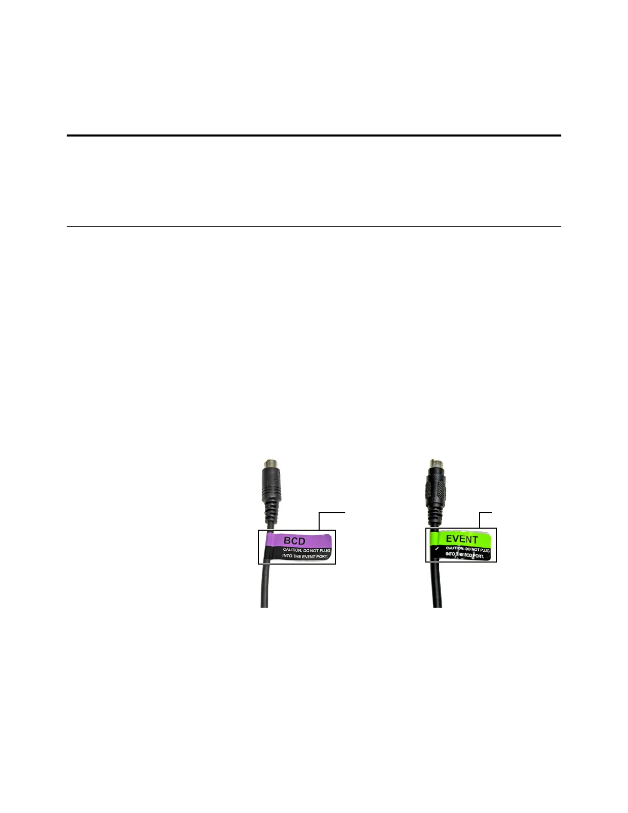
Labeling BCD and EVENT cables
The BCD and EVENT connectors look similar. However, plugging
an Event cable into the BCD connector can damage the GC logic
board. To prevent accidental damage, the following BCD and
Event cables come with labels that identify their intended use:
• G1580-60710, External valve cable
• G1580-60730, Pulser Module Power Supply Cable
• G1580-61100, BCD Cable Assembly
For other cables, apply an Event or BCD label to the cable:
• G1580-87100, Caution label, BCD cable, purple
• G1580-87200, Caution label, Events cable, green
Configuring the GC IP address
For network (LAN) operation, the GC needs an IP address. It
can be entered directly from the keyboard (recommended if
using an Agilent data system) or obtained from a DHCP server
(not recommended). In either case, see your LAN administrator.
Tabl e 8 Cabling for other instruments in a 7890 Series GC system
Instrument 1 Instrument 2 Type of cable Part number
Mass Selective Detector Purge & trap, thermal
desorber, or headspace
sampler
Splitter ("Y") cable for remote
start/stop, 1 male and 2 female
connectors
G1530-61200
Splitter ("H") cable for APG remote, 2
male and 2 female connectors
35900-60800

 Loading...


