Agilent 7890B Installation 3
Contents
1 Installing the GC
Overview of Installation 8
Purpose of this procedure 8
Customer responsibilities 8
About Agilent’s installation service 8
Tools and additional parts required 9
Performing checkout 9
System installation 9
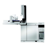
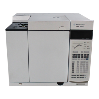
The 7890B GC 11
Unpacking 12
Step 1. Place the GC on the bench 13
Step 2. Verify line voltage, voltage settings, and power cord. 14
Power consumption 14
Power cords available 15
Grounding 19
Line voltage 19
Line power cord terminations 19
Step 3. Connect the power cord and turn on the GC 20
Step 4. Connect gases and traps 22
Install the gas regulators 22
Connect the tubing to the gas source 24
Install traps 25
Supplied fittings 26
Plumb to EPC flow modules 26
Install Aux EPC module frits for your application 30
Install hydrogen sensor calibration gas 31
Step 5. Leak test all connections and set source pressures 33
Set source gas pressures 35
Step 6. Vent µECD or uncombusted hydrogen to a fume hood 36
Step 7. Connect cryogenic cooling (if present) 37
Connecting liquid carbon dioxide 38
Connecting liquid nitrogen 40
Connecting air to the multimode inlet 41
Step 8. Connect valve actuator air (if present) 42
Step 9. Install inlet checkout parts 43
Step 10. Install ALS, if ordered 44

 Loading...
