Cabling Diagrams and Remote Start/Stop B
Agilent 7890B Installation 87
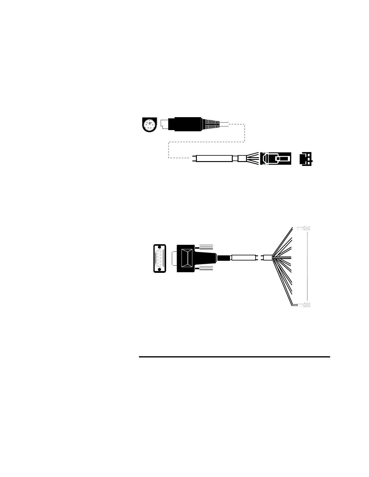
Agilent analog signal cable, G1530-60570
This cable connects an Analog out port to an external data
system. Both 0 to 1 volt and 0 to 10 volts are provided. Connects
both GC signal outputs to Agilent 3395B/3396C integrators, and
the 35900 A/D.
Figure 24 Analog output cable to an Agilent product
Remote start/stop cable, general use, 35900-60670
The pin assignments for the remote start/stop cable are listed in
Table 11.
Tabl e 1 1 Remote start/stop cable connections
Connector 1, 9-pin male Connector 2, wire color Signal
1 Black Digital ground
2 White Prepare (low tone)
3RedStart (low tone)
4 Green Start relay (closed during
start)
35900-60670
1
6
5
9
Connector 1
Connector 2

 Loading...


