EasyManuals Logo

Agilent Technologies 7890B Installation And Startup

Agilent Technologies 7890B
94 pages
To Next Page IconTo Next Page
To Previous Page IconTo Previous Page
Page #90 background imageLoading...
Page #90 background image
90 Agilent 7890B Installation
B Cabling Diagrams and Remote Start/Stop
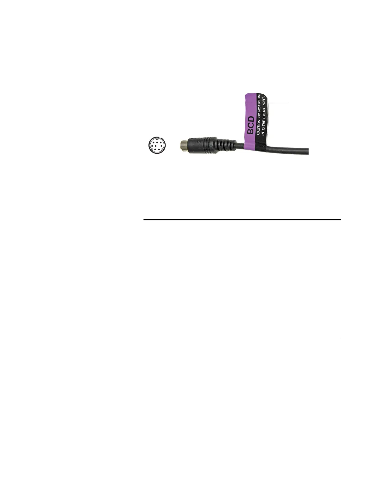
BCD cable, G1530-60590
The BCD cable connector has eight passive inputs that sense
total binary-coded decimal levels. The pin assignments for this
connector are listed in Table 12.
When used for BCD input, apply label G1580-87100 to identify
the cable for BCD use.
Tabl e 1 2 BCD input connections
Pin Function Maximum rating
1 Relay 48 V AC/DC, 250 mA
2 Relay 48 V AC/DC, 250 mA
3 LS digit 0
4 LS digit 1
5 LS digit 2
6 LS digit 3
7MS digit 0
8Ground
Shield Chassis ground
Apply label
G1580-87100
2
8
1
6

Table of Contents

Other manuals for Agilent Technologies 7890B

Questions and Answers:

Question and Answer IconNeed help?

Do you have a question about the Agilent Technologies 7890B and is the answer not in the manual?

Agilent Technologies 7890B Specifications

General IconGeneral
BrandAgilent Technologies
Model7890B
CategoryLaboratory Equipment
LanguageEnglish

Related product manuals