48 Agilent 7890B Installation
1 Installing the GC
Connecting cables
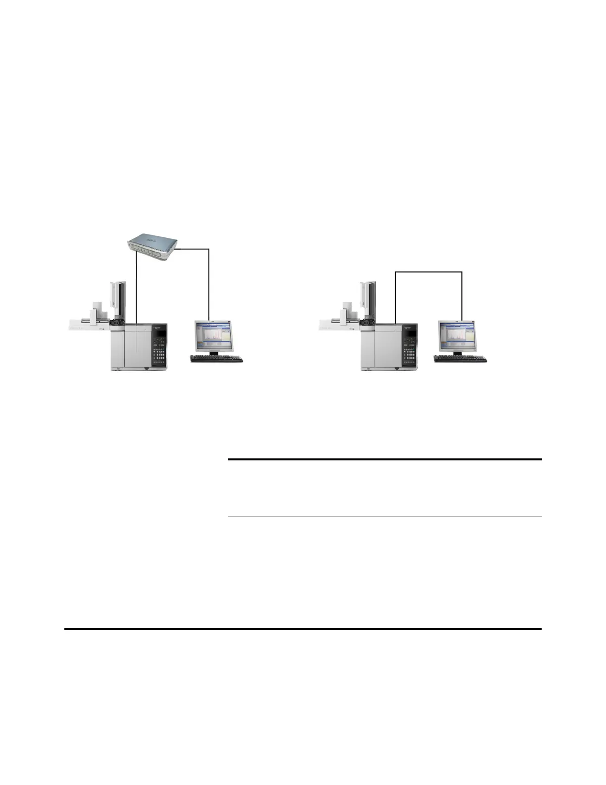
Use the supplied LAN cable to connect the GC to a LAN switch
or hub as shown below (see Figure 16). Other LAN
configurations are possible. However Agilent typically supports
only simple LAN setups. Refer to your Agilent data system
documentation for details about its supported LAN
configurations.
Figure 16 Simple supported LAN configurations: LAN switch or hub (left) and direct connection (right)
A single LAN communications cable is supplied with the GC.
The switch (or hub) and other cables must be ordered
separately, if needed. See Table 6 and Table 7 for cabling
requirements for other configurations.
LAN switch or hub
LAN cable
8121-0940
Crossover LAN cable 5183-4648
GC GCComputer Computer
LAN cable
8121-0940
OR
Tabl e 6 Typical IP addresses for an isolated LAN
GC Computer
IP address 10.1.1.101 10.1.1.100
Subnet mask 255.255.255.0 255.255.255.0
Tabl e 7 Cabling requirements
7890 Series GC connected to: Required Cable(s) Part number
Samplers
7693A Automatic Liquid Sampler Injector cable or tray cable G4514-60610
7650 Automatic Liquid Sampler Injector cable G4514-60610

 Loading...


