Cabling Diagrams and Remote Start/Stop B
Agilent 7890B Installation 93
When used for external event control, apply label G1580-87200
to identify the cable for EVENT use.
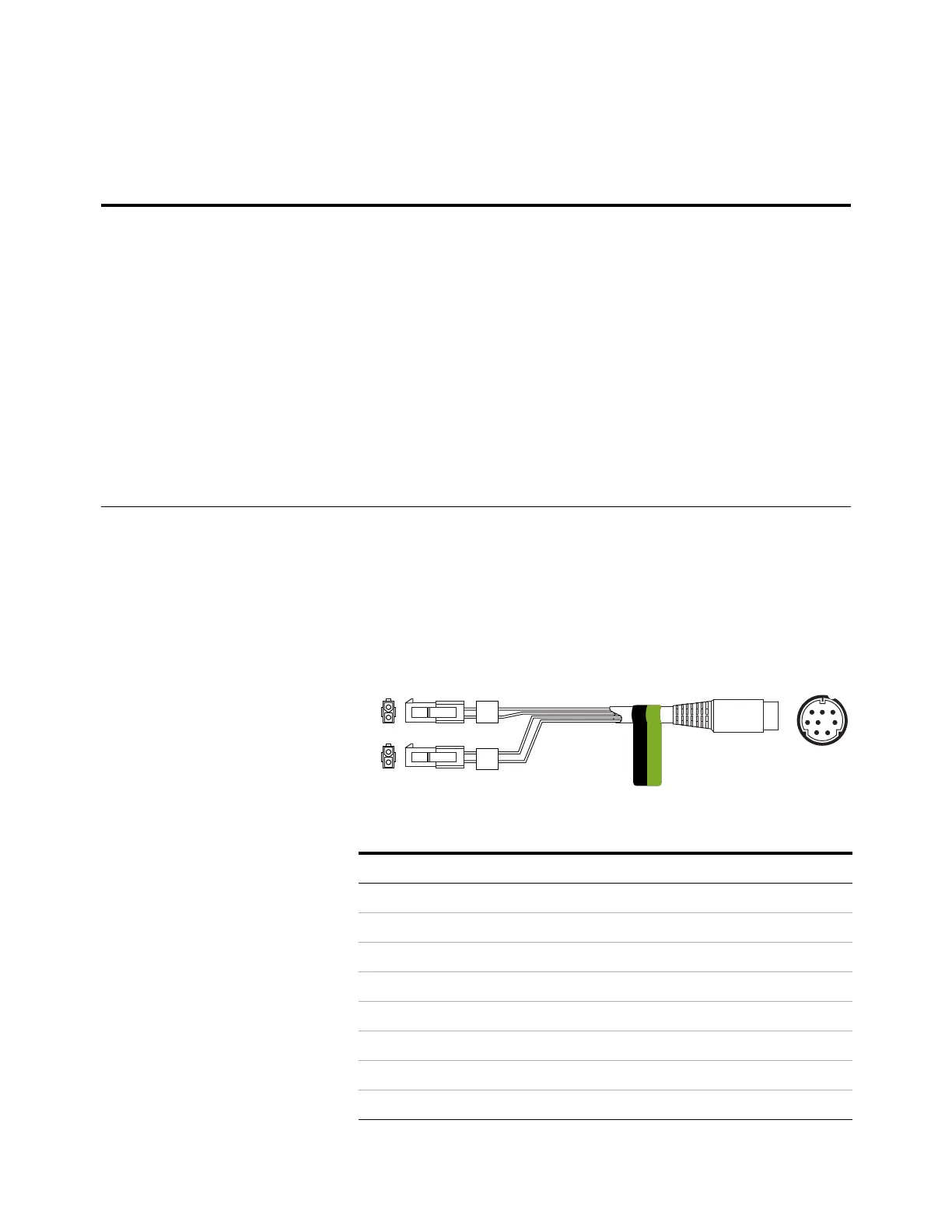
External valve cable, G1580-60710
Supplies power for certain valve applications.
Tabl e 1 4 External events cable
Connector 1 pin Signal name Maximum rating Connector 2, wire color Controlled by valve #
24 volts output
1 24 V output 1 150 mA Yellow 5
2 24 V output 1 150 mA Black 6
3Ground Red
4Ground White
Relay contact closures
(normally open)
5 Closure 1 48 V AC/DC, 250 mA Orange 7
6Closure 1 Green7
7 Closure 2 48 V AC/DC, 250 mA Brown or violet 8
8Closure 2 Blue8
Connector 1 pin Wire color Connector and pin Function
1 Yellow V5 pin 1 24 V, 150 mA max.
2 Black V6 pin 1 24 V, 150 mA max.
3 Red V5 pin 2 Ground
4 White V6 pin 2 Ground
5
6
7
8
2
1
2
1
EVENT
CAUTION: DO NOT PLUG
INTO THE BCD PORT.
V5
V6

 Loading...


