7
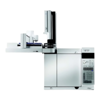
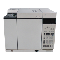
Agilent 7890B Gas Chromatograph
Installation and First Startup
Agilent Technologies
1
Installing the GC
Overview of Installation 8
The 7890B GC 11
Unpacking 12
Step 1. Place the GC on the bench 13
Step 2. Verify line voltage, voltage settings, and power cord. 14
Step 3. Connect the power cord and turn on the GC 20
Step 4. Connect gases and traps 22
Step 5. Leak test all connections and set source pressures 33
Step 6. Vent µECD or uncombusted hydrogen to a fume hood 36
Step 7. Connect cryogenic cooling (if present) 37
Step 8. Connect valve actuator air (if present) 42
Step 9. Install inlet checkout parts 43
Step 10. Install ALS, if ordered 44
Step 11. Connect the external cables 45
Step 12. Finish configuring communications 53
Step 13. Calibrate the Hydrogen Sensor 58
Step 14. Configure the date/time, pressure units, and the checkout
column 59
Step 15. Install the checkout column to the inlet and condition 61
Step 16. Bakeout the detector 63
Step 17. Cool the detector and complete column installation 64
Step 18. If appropriate, update firmware 65
Step 19. Transfer the checkout sample to a screw-top sample vial 67
Step 20. When the system stabilizes, run one injection 68
Step 21. Evaluate Results 69
Prepare for the Next Analysis 70
This section contains installation procedures for the Agilent
7890B GC. Depending on the ordered options, some steps are
optional, such as plumbing cryogenic cooling or valve actuator
air.
Instructions for connecting cables from the GC to other
instruments in a typical 7890 Series system are included here
and in Appendix B, “Cabling Diagrams and Remote Start/Stop."

 Loading...
