2- 13
Making Mixer Measurements
Conversion Loss Using the Frequency Offset Mode
Conversion Loss Using the Frequency Offset Mode
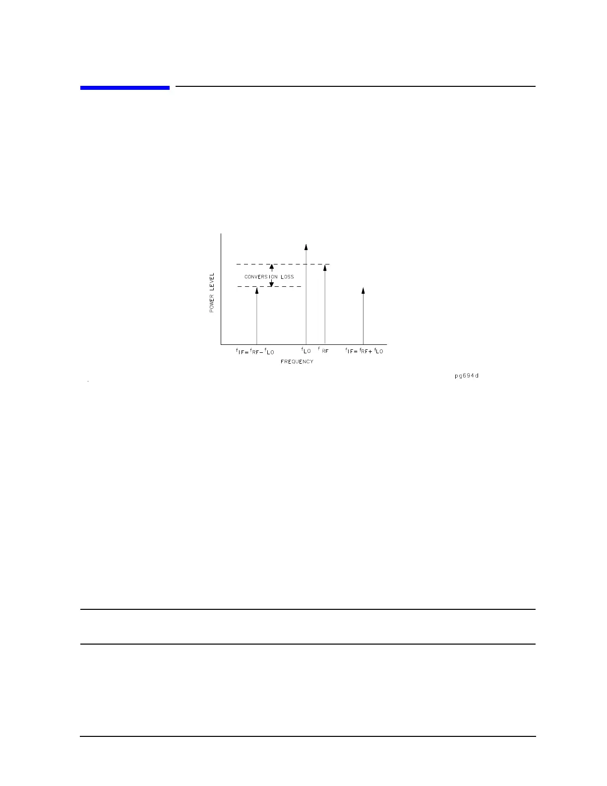
Conversion loss is the measure of efficiency of a mixer. It is the ratio of side-band IF power to RF signal
power, and is usually expressed in dB. The mixer translates the incoming signal, (RF), to a replica, (IF),
displaced in frequency by the local oscillator, (LO). Frequency translation is characterized by a loss in signal
amplitude and the generation of additional sidebands. For a given translation, two equal output signals are
expected, a lower sideband and an upper sideband.
Figure 2-10 An Example Spectrum of RF, LO, and IF Signals Present in a Conversion Loss
Measurement
The following procedure describes the R channel swept IF frequency conversion loss measurement of a
broadband component mixer with power meter calibration. For this example, we will use the following
example settings. For your measurement, you will need to use settings specific to your measurement.
Settings Used for this Example
• LO frequency of 1 GHz (1000 MHz)
• RF start frequency of 650 MHz
• RF stop frequency of 900 MHz
• IF start frequency of 100 MHz
• IF stop frequency of 350 MHz
•RF < LO
• Down convertor
TIP For ease of use, the RF frequency range needs to be the same as the network analyzer’s
frequency range limit.

 Loading...


