6- 15
Calibrating for Increased Measurement Accuracy
Frequency Response Error Corrections
NOTE You can save or store the measurement correction to use for later measurements. Refer to
the Chapter 4 , “Printing, Plotting, and Saving Measurement Results” for procedures.
7. This completes the response correction for transmission measurements. You can connect and measure
your device under test.
Receiver Calibration
Receiver calibration provides a frequency response error correction for a non-ratioed measurement that also
indicates absolute power in dBm. This calibration is most useful when performed with a power meter
calibration. This calibration is only allowed for non-ratioed measurements A, B, and R.
This calibration normalizes the trace to the current reference value. Typically, this reference value is entered
to be the same as the current source power.
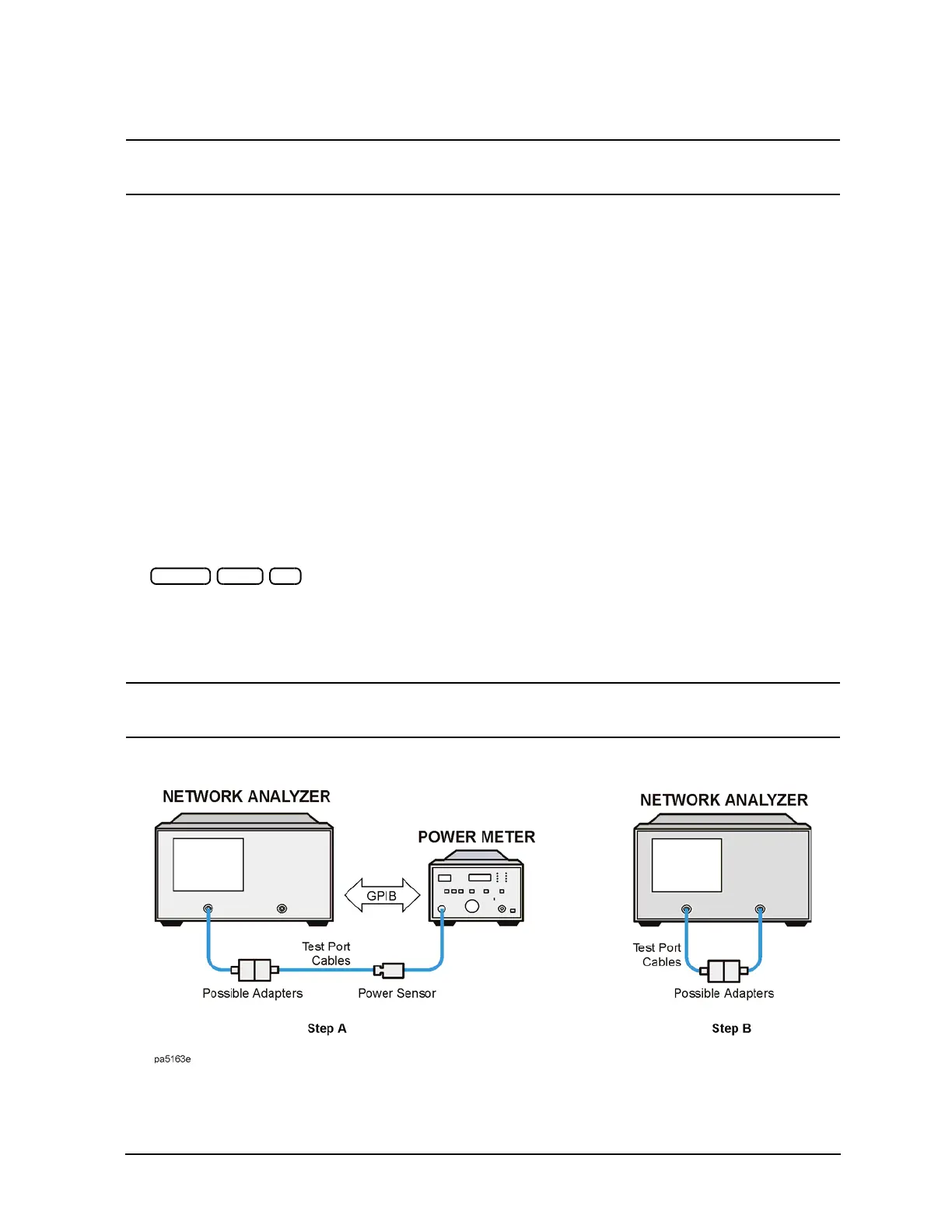
1. Perform a power meter calibration to the desired level. Refer to step A of Figure 6-4. Use 10 dBm for this
example. (See also, "Power Meter Measurement Calibration" on page 6-33.) This provides a calibrated
power, referenced to the power meter, to use as a receiver calibration standard.
or
Set the analyzer test port power to the desired level (10 dBm in this example) by pressing:
. This calibrates the receiver to the approximate accuracy of the source output
power, which is subject to the source power flatness specification.
2. Make a "thru" connection between the points where you will connect your device under test. Refer to
Step B of
Figure 6-4.
NOTE Include any adapters or cables that you will have in the device measurement. That is,
connect the standard device where you will connect your device under test.
Figure 6-4 Standard Connections for a Receiver Calibration
3. To choose a non-ratioed measurement, press:

 Loading...


