1- 121
Making Measurements
Single Connection Multiple Measurement Configuration (Option 014 Only)
Single Connection Multiple Measurement Configuration
(Option 014 Only)
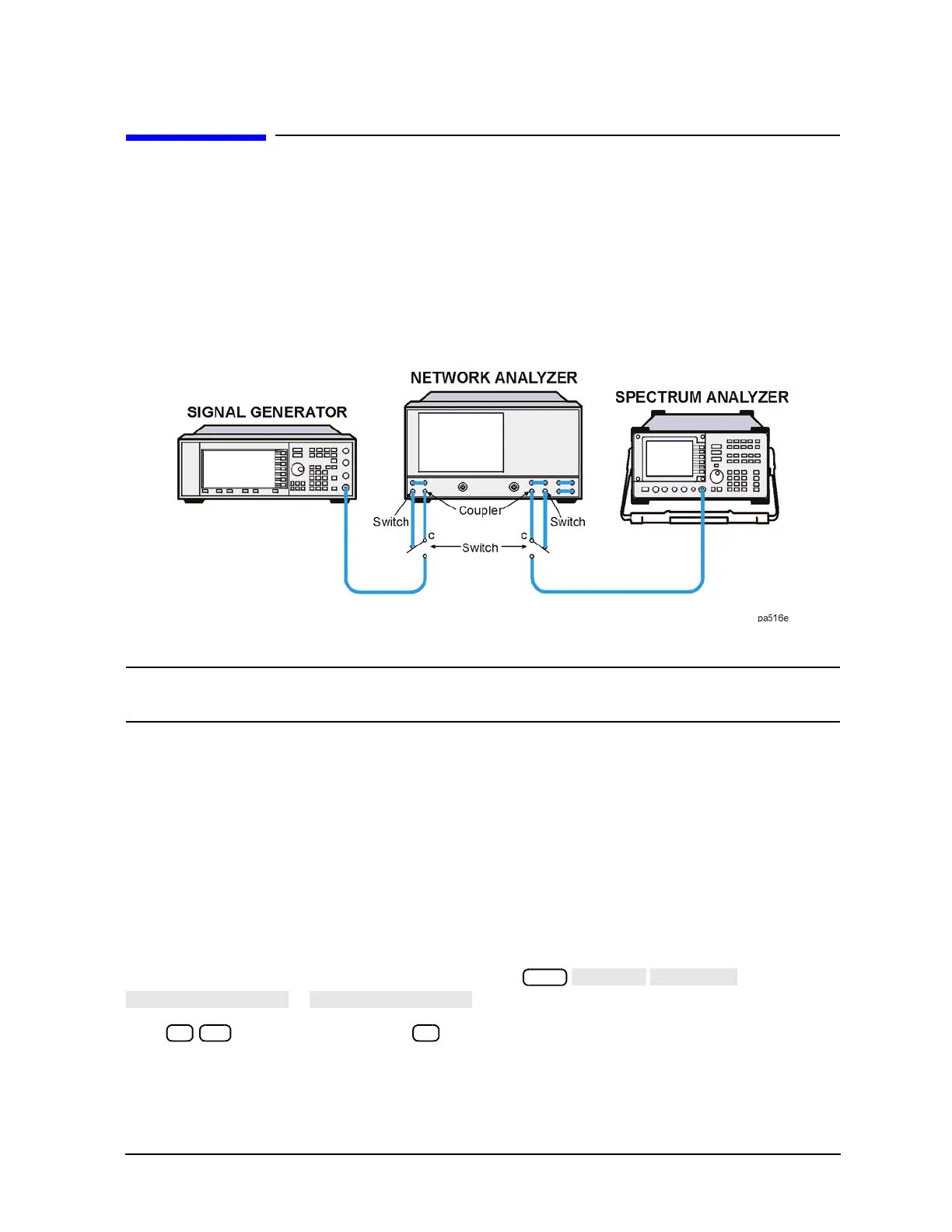
Single connection multiple measurements (SCMM) can be configured with Option 014 analyzers. Using the
PORT 1 SWITCH/COUPLER and the PORT 2 SWITCH/COUPLER ports, you can insert a switch which can
then connect other test instruments through the analyzer to the DUT. This makes it easy to make several
different types of measurements without having to disconnect your device under test from the test ports.
Refer to
Figure 1-82.
Figure 1-82 Single Connection Multiple Measurement Configuration
NOTE The common port of the external switches MUST be connected to the PORT 1 and PORT 2
COUPLER access PORTS.
External switches can be controlled by an external switch driver like the HP/Agilent 11713A
Attenuator/Switch Driver. The TEST SET-I/O INTERCONNECT connector located on the rear panel of the
analyzer, can also control external switches. Refer to
Figure 1-81 on page 1-111. Table 1-6 on page 1-112
contains a complete list of this connector’s pins.
Controlling External Switches
The following are different ways to control the external switches used in the SCMM mode of operation. The
analyzer is used as the controller.
Manual
The test set I/O may be set using the following keystrokes:
or
Enter for external operation and for normal or standard operation.
Sequencing Program:
The test set I/O may be set using the test sequencing function in the analyzer. The following is an example

 Loading...


