106 Chapter 4
Troubleshooting the RF Section (E4446A, E4447A, E4448A)
RF Section Description (E4446A, E4447A, E4448A)
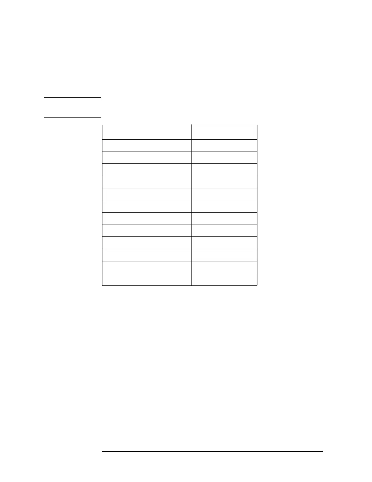
With the PSA set to a center frequency below 3 GHz, and in zero span,
check that the bias voltages are present. Some of these can be accessed
on the A13J12 Test Connector and some others have test points. With
the negative lead of the DVM on A13J12 pin 6, look for values listed in
the table.
CAUTION Use care when probing connector pins on A13, especially on A13J8.
Connector spacings are close and shorting nodes can cause damage.
The remaining biases are 2
nd
_LO_PIN and 2
nd
_LO_ATTEN. Since
these are currents they cannot be directly measured at the Lowband
assembly connector. The output of the DAC which controls this ALC
circuit on A13 is A13TP25. To help verify that this part of the circuitry
which drives the Lowband assembly is functioning correctly, perform
the 2
nd
LO Power adjustment.
Pin/ Name Nominal Voltage
A13J12 pin1/−5V_F −5 V
A13J12 pin2/−5V_M1LO −5 V
A13J12 pin3/−5V_M1IF −5 V
A13J12 pin4/−5V_M2LO −5 V
A13J8 pins 7,8/+3V_LB 3 V
A13J8 pin25/+5.2V_LB 5.2 V
A13J8 pin16/+10V_LB 10 V
A13TP22/M1LO_ADJ 100 mV
A13TP23/M1IF_ADJ 150 mV
A13TP24/M2LO_ADJ 100 mV
A13TP26/LO_NULL_I_DAC −5 to +5 V
A13TP27/LO_NULL_Q_DAC −5 to +5 V
 Loading...


