Chapter 11 371
Assembly Replacement Procedures
Vertical Board Assemblies (Standard Instrument)
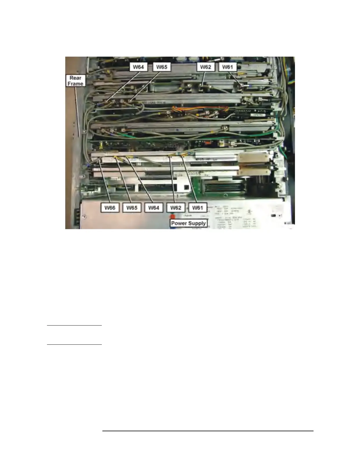
Figure 11-42 Option 122 or 140 Cable Routing
Removal
If you haven’t already done so, remove the instrument outer case and
top brace. Refer to the “Instrument Outer Case” and the “Top Brace”
removal procedures.
To remove any of the vertical board assemblies, it will be necessary to
remove the cables attached to that assembly. After the cables are
removed, pull up on the ejector tabs to unseat the board from the
motherboard connector, then slide the board up to remove it from the
deck.
NOTE For E4447A A10 3rd Converter assembly, the cable on J2 cannot be
removed! See below for the 3rd Converter removal procedure.
For Option 122 or 140 assemblies and cables, see Figure 11-41. Remove
W60 ribbon cable before removing either A31 or A32 assemblies.
To remove the A12 LO Synthesizer assembly, it will also be necessary to
remove the cable hold down wire (single screw), and the two screws
attaching the assembly to the midweb and deck.
 Loading...


