Chapter 3 81
Troubleshooting the RF Section (E4440A, E4443A, E4445A)
RF Section Description (E4440A, E4443A, E4445A)
Common failures with RYTHM are a damaged input switch due to
input overstress, and a faulty preselector. The former can cause signal
loss in either High Band or Low Band, or in both. The latter will cause
signal loss or flatness problems in High Band only.
Whenever a RYTHM is suspected, first check presence of the –15VF
bias at A13J6 pin 5, and +15VF at A13J6 pin 7 using a DVM. Connect
the negative lead of the DVM to A13 TP8. Voltages and signals coming
from A13J6 should also be checked at the RYTHM to verify W28. Check
that the LO from A18 through W35 is present using another spectrum
analyzer. Also check the input signal coming through W9 from the
attenuator. (The signal level will be the input level less the attenuator
settings.) If you are using the internal 50 MHz calibrator signal, make
sure that it is switched in.
If the signal is corrupted in Low Band only, make sure that the input
switch is being controlled after verifying presence of the input signal.
HIBAND should be a TTL high in High Band and low in Low Band.
If the signal is not getting through the preselector, first check the band
switching per the above paragraph. Try manually peaking the signal by
pressing
AMPLITUDE, Presel Adjust. If the signal can be peaked, the
flatness adjustment may be needed or the A13 is faulty. A faulty
RYTHM is least likely in this scenario. Next check the presence of a
tune ramp. Set the start and stop frequencies to 3 GHz and 26.5 GHz
respectively with the PSA in continuous sweep. (This generates a ramp
to tune the preselector nearly through its entire range.)
The A13 YTF tune circuitry can be quickly verified by looking for a
combination of steps and ramps ranging from approximately 0 to 5 volts
with an oscilloscope on the rear panel PRE-SEL OUT connector. The
period of this waveform will vary with the sweep time. Also verify that
+VTUNE is being applied to the RYTHM at A13J6 pin 13. A similar
ramp ranging up to about 2.5 volts should be observed.
A18 YTO
The YTO (YIG-Tuned Oscillator) supplies the raw 3 to 7 GHz LO signal.
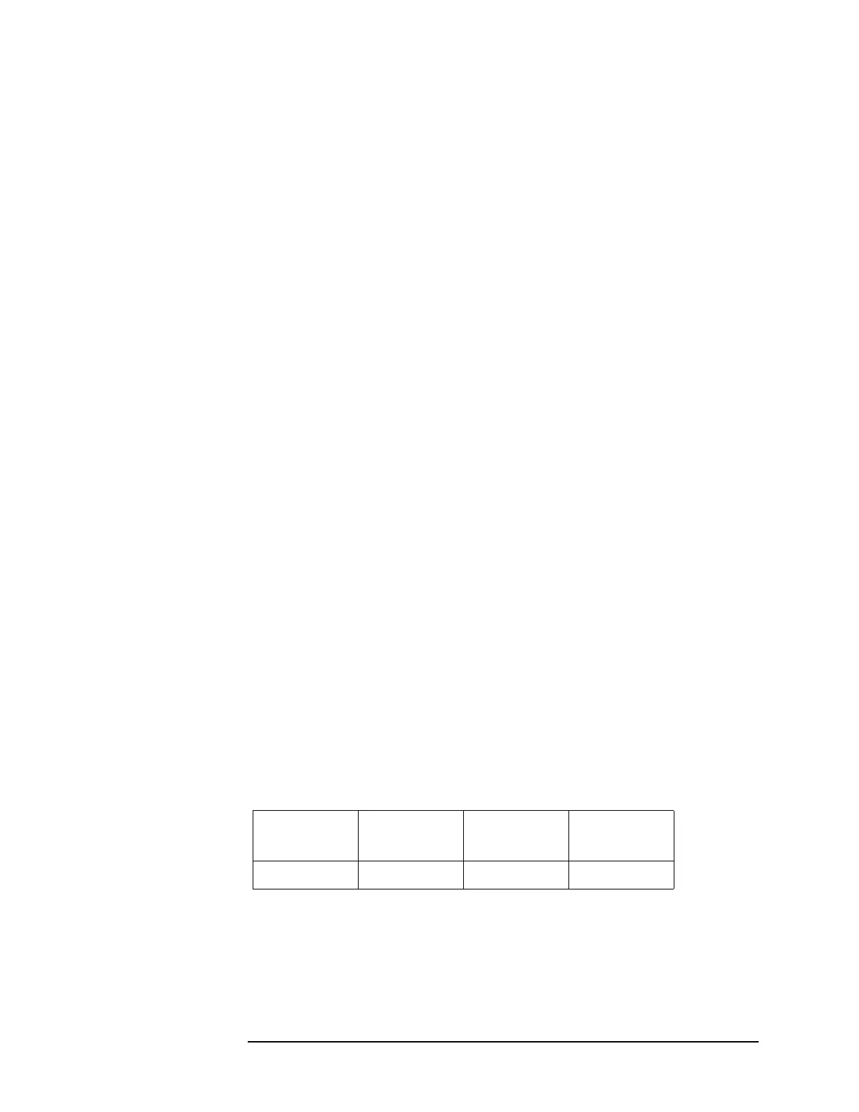
Verify that its output is from +12 dBm to +17 dBm. With a DVM, verify
the presence of the supplies on the A13 Front End Driver:
Common symptoms of a faulty YTO are YTO Unlock errors, spurious
signals, and low signal level at all frequencies. Two current-driven coils
are used to tune the YTO. Both coils are used in all spans. The coil
drivers are on the A12 LO Synthesizer assembly and the signals route
through the A13 Front End Driver.
J7
Pin 4
J7
Pin 5
J7
Pin 7
J7
Pin 9
+15 V −5 V +15 V +15 V
 Loading...


