82 Chapter 3
Troubleshooting the RF Section (E4440A, E4443A, E4445A)
RF Section Description (E4440A, E4443A, E4445A)
A20 Lowband
The Lowband assembly is the front end converter for frequencies below
3 GHz. The Lowband assembly encompasses both the first and second
mixers, the 2
nd
LO multiplier, LO Nulling and filtering.
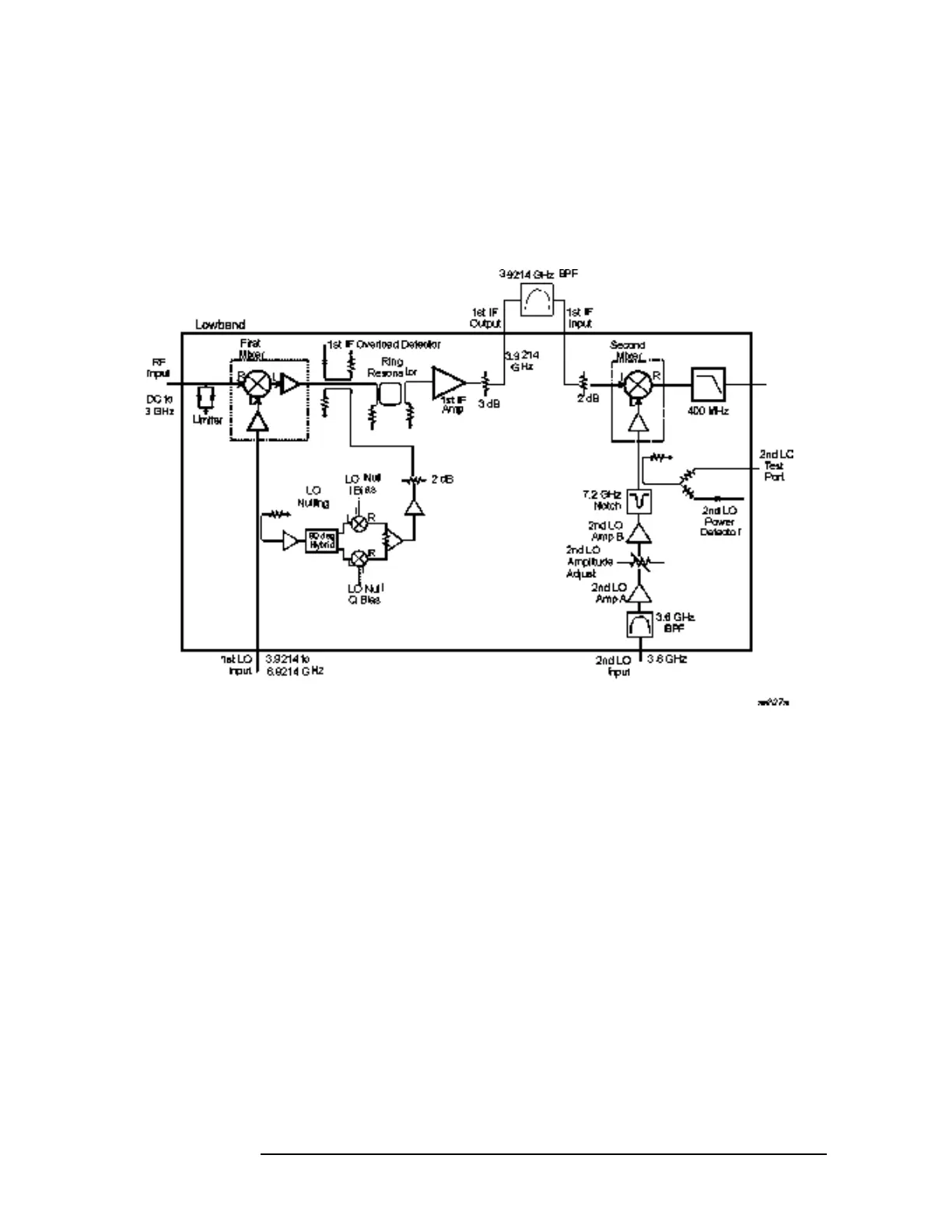
Figure 3-7 Lowband Assembly Block Diagram
The 3 Hz to 3 GHz RF input signal enters the Lowband assembly at
A20J1. The first component in the RF path is the RF Limiter. This
limiter prevents excessive RF energy from damaging the first mixer.
The first mixer up-converts the 3 Hz to 3 GHz signal to the 3.9214 GHz
first IF. The first LO, which enters the Lowband assembly from the
SLODA, ranges from 3.9214 to 6.9214 GHz. Following the first mixer is
a dual coupler. One output of the coupler routes to the first IF overload
detector and the other coupler port is the input from the LO Nulling
circuit. The next stage in the first converter section is the First IF
Amplifier. Following the First IF Amplifier, the first IF signal leaves
the Lowband assembly, routes through the external first IF bandpass
filter and re-enters the Lowband assembly in the Second Converter
section. The second mixer down-converts the 3.9214 GHz first IF to the
321.4 MHz second IF. The second LO is at 3.6 GHz. Following the
Mixing equation: F
LO
= F
RF
+ F
IF
F
IF
= 3.9214 GHz
 Loading...


