78 Chapter 3
Troubleshooting the RF Section (E4440A, E4443A, E4445A)
RF Section Description (E4440A, E4443A, E4445A)
A21 Switched LO Distribution Amplifier (SLODA)
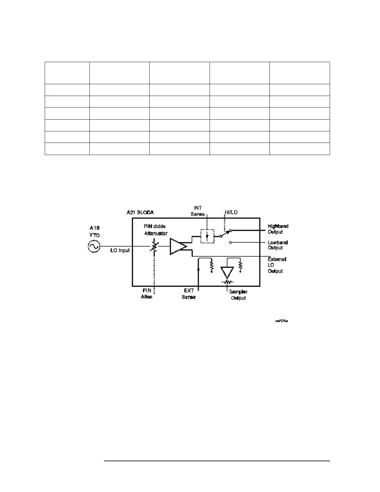
Figure 3-6 SLODA Block Diagram
The A21 SLODA provides amplitude leveling and distribution of the 3
to 7 GHz first LO signal to the RYTHM, Lowband assembly, and LO
Synthesizer Board (Sampler output). The External LO Output is
terminated in 50 Ohms.
The 3 to 7 GHz LO signal enters the SLODA from the YTO. The ALC
circuit on the A13 Front End Driver provides level control via the PIN
Atten line. The ALC circuit receives its input from the SLODA’s INT
Sense line. The A13 also provides the RYTHM band and Low Band
switching information as well as Gate Bias.
Some common symptoms of a faulty SLODA include YTO Unlock
errors, Sampler errors, LO Unleveled errors, low signal level in one or
both bands, spurious signals or high DANL. To verify a faulty SLODA,
first check that the YTO signal is present at the YTO IN connector. The
Table 3-2 A14 Settings
Attenuation
(dB)
2 dB_A
Select J3 pin 8
2 dB_A
Bypass J3 pin 5
2 dB_B
Select J3 pin 7
2 dB_B
Bypass J3 pin 6
0 High Low High Low
2 Low High High Low
4 Low High Low High
6 High Low High Low
8 Low High High Low
10 High Low High Low
 Loading...


