Chapter 11 365
Assembly Replacement Procedures
A39 USB/Memory Board
Replacement
1. Insert the USB/Memory board, making sure to firmly insert the
connectors into the PSA motherboard sockets, but do not exert so
much force as to break the connector.
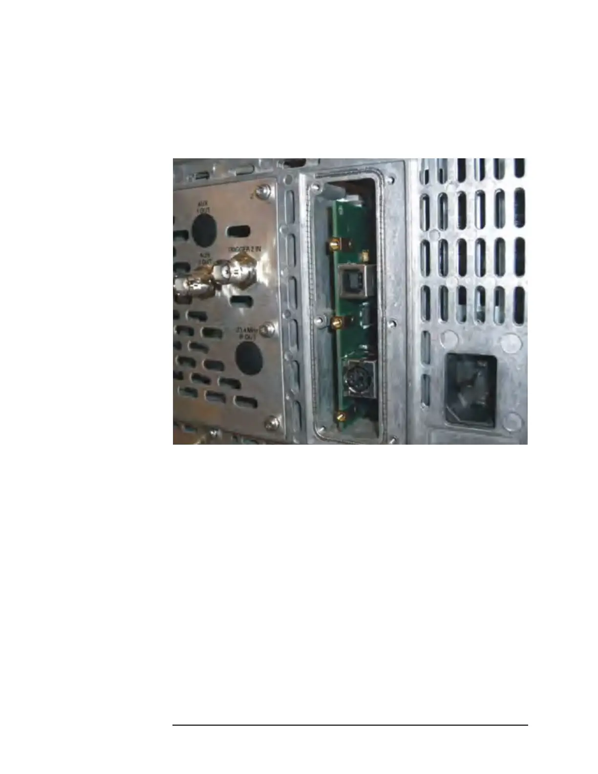
2. After installation, the memory board should look like this:
3. Put the rear plate in place on the PSA rear panel, and screw it into
place.
4. Replace the instrument top brace. Refer to the “Top Brace”
replacement procedure.
 Loading...


