Chapter 4 101
Troubleshooting the RF Section (E4446A, E4447A, E4448A)
RF Section Description (E4446A, E4447A, E4448A)
A19 SBTX/RYTHM Assembly
The A19 assembly is comprised of the SBTX (switched barium-ferrite
tuned filter/mixer), and the RYTHM (routing yig-tuned harmonic
mixer). The SBTX and the RYTHM are not separately replaceable. The
SBTX provides a switch that routes the input signal to the RYTHM
(high band and low band signals) or through the SBTX preselector and
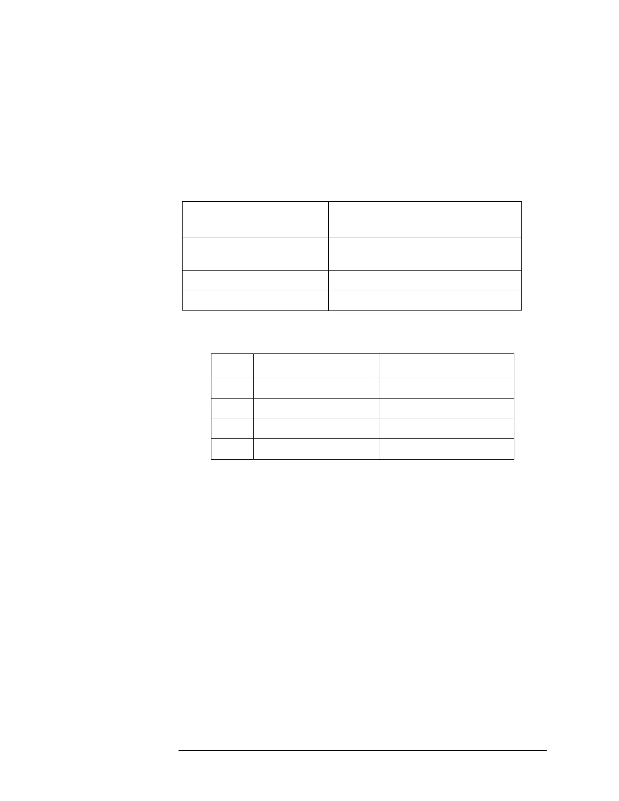
mixer (mm band path). The following table lists the frequencies where
the switch points occur.
The RYTHM bands are bands 1 through 4 whose start (minimum) and
stop (maximum) frequencies are shown in the following table:
The mixing equations are:
Center Frequency
(Instrument in zero span) Signal Routed to First Mixer on:
3 Hz to 3 GHz Low band
(through SBTX and RYTHM switches)
3.05 GHz to 26.8 GHz RYTHM
> 26.8 GHz SBTX
Band Minimum Frequency Maximum Frequency
1 2.85 GHz 6.6 GHz
2 6.2 GHz 13.2 GHz
3 12.8 GHz 19.2 GHz
4 18.7 GHz 26.5 GHz
Band 1 F
LO
= F
RF
+ F
IF
Band 2 F
LO
= (F
RF
+ F
IF
)/2
Band 3, 4 F
LO
= (F
RF
+ F
IF
)/4
F
IF
= 321.4 MHz
 Loading...


