100 Chapter 4
Troubleshooting the RF Section (E4446A, E4447A, E4448A)
RF Section Description (E4446A, E4447A, E4448A)
Verifying the A29 SBTX/FELOMA Driver Assembly
Test points are provided on the A29 SBTX/FELOMA Driver board that
allow you to confirm the DC drive levels to the FELOMA assembly are
correct. There is a label on the FELOMA assembly that lists the target
voltages in milli-volts. Access to the test points is gained by sliding the
A29 assembly out of the instrument slightly.
1. Power down the instrument to avoid shorting out the A29 assembly
while it is being unseated from the RF chassis.
2. Pull up on the stainless steel spring clip near the center of the
assembly, and pull forward on the A29 bracket to slide the assembly
1 to 2 inches out of the instrument.
3. Locate test point 2 near the back of the board, and connect the DVM
ground lead to TP2.
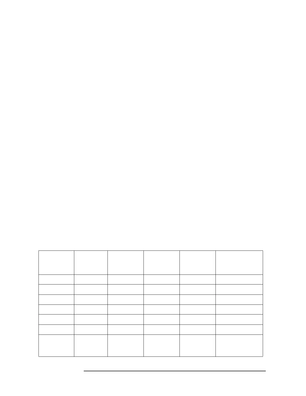
4. Connect the other DVM test lead to one of the test points listed in
Table 4-4.
5. Assure the A29 assembly is supported well and cannot short out
against anything.
6. Turn on the instrument and set it to zero span and set the center
frequency to correspond to the test point chosen in Table 4-4.
7. Compare the DVM reading to the value documented on the
FELOMA label. The values should match ± 0.005 volts, except for
the Int B5 and Int B6 values that must be less that −275 mv, but are
usually close to the −350 mv label.
Table 4-4 A29 SBTX Driver Board DC Levels To Be Compared With
FELOMA Label
PSA
Center
Frequency
TP5
VG1
(mv)
TP12
VG2
(mv)
TP9
LO Level
(mv)
TP4 SBTX
Unleveled
(mv)
TP11
“S” Sampler
Unleveled (mv)
50 MHz VG1 VG2 Band0 NA S
4 GHz VG1 VG2 Band1 NA S
10 GHz VG1 VG2 Band2 NA S
20 GHz VG1 VG2 Band3/4 NA S
30 GHz NA NA IntB5 SBTX B5 S
50 GHz NA NA IntB5 SBTX B6 S
External
Mixing
Frequency
NA NA “F” Label
Value
NA NA
 Loading...


