Chapter 4 109
Troubleshooting the RF Section (E4446A, E4447A, E4448A)
RF Section Description (E4446A, E4447A, E4448A)
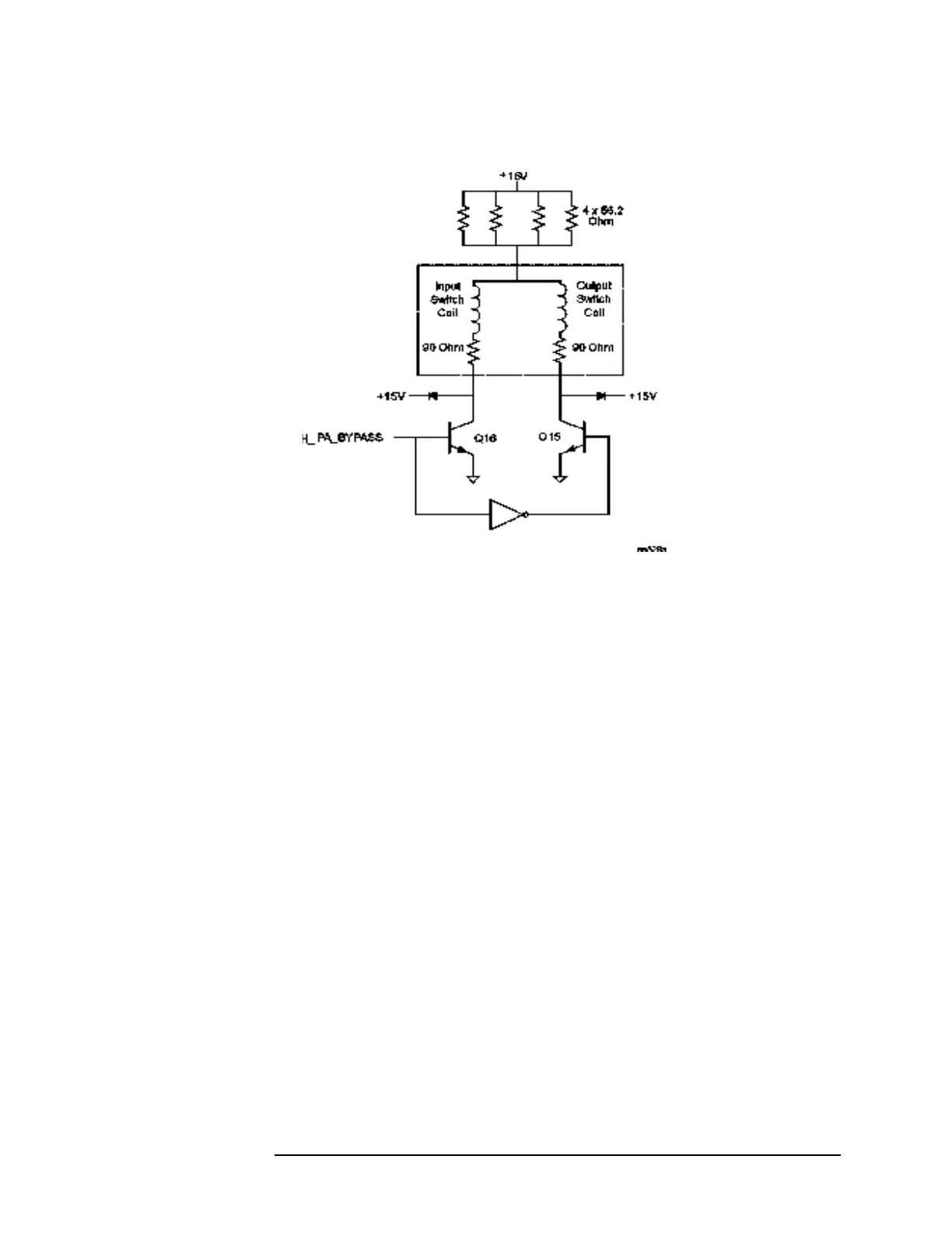
Figure 4-10 Coax Switch Bias Circuit
A27 Electronic Attenuator Description (Option B7J)
Purpose: The electronic attenuator facilitates the accurate, frequent,
and rapid attenuation that is optimal for digitally modulated signals.
The attenuator supplies 40 dB of attenuation in 1 dB steps.
The instrument must be in Basic mode to allow front panel control of
the electronic attenuator. Press
MODE, Basic, Input/Output, Input Atten.
The electronic attenuator is actuated by the instrument firmware
during comms measurements.
Signal Path: The low band signal is routed from the RYTHM. A switch
in the electronic attenuator selects either the bypass path, or the
attenuation path. The output signal is routed to the A20 Low Band
assembly.
Troubleshooting: Select Spectrum Analysis mode. Apply a 50 MHz
input signal to the analyzer and select zero span. Measure the signal on
the W51 input cable after detaching it from the input connector.
Reattach the input cable and measure the power out of the attenuator
at J2. In Spectrum mode, the attenuator pads should be bypassed and
the output power should be input power minus 0.2 to 0.3 dB.
Select Basic mode. Press
Input/Output and select Input Port Amptd Ref.
Set the analyzer center frequency to 50 MHz to display the internal
calibration signal. Vary the input attenuation from 0 dB to 40 dB. The
displayed amplitude should vary by less than 1 dB.
 Loading...


