86 Chapter 3
Troubleshooting the RF Section (E4440A, E4443A, E4445A)
RF Section Description (E4440A, E4443A, E4445A)
A22 Low Band Preamplifier (Option 1DS)
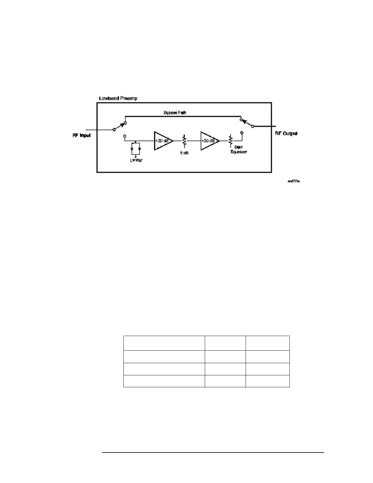
Figure 3-9 Preamplifier Block Diagram
The Low Band Preamp has a nominal gain of 30 dB and contains two
electro-mechanical coax switches. The frequency range of the preamp is
100 kHz to 3 GHz. The input signal level at the preamp should not
exceed −30 dBm. To verify its operation, display the −25 dBm, 50 MHz
calibrator signal on screen with a 5 MHz span and the input attenuator
set to 10 dB. Select the Low Band Preamp path by pressing
AMPLITUDE,
More, Int Preamp On, (listen for a distinctive “click”) and measure the
signal levels at the input and output with a spectrum analyzer. Also,
the displayed signal on the PSA should not change position when the
preamplifier is switched in and out, but the noise floor will decrease
with the preamp on. Please note that the RF attenuator value may
increase, depending on the reference level, causing the noise floor to
increase.
The preamp is controlled by supply biases and coax switch voltages. A
nominal +9 volts should be present at A13J9 pins 2 and 3. Switch
voltages can be checked per the table (the ribbon cable must remain
attached).
Node Off Volts On Volts
A13J9 pins 18,19 +COIL 13 13
A13J9 pin 20 SW1 0.3 13
A13J9 pin 17 SW2 13 0.3
 Loading...


