376 Chapter 11
Assembly Replacement Procedures
Fans/Mid Web
Mid Web
To completely remove the mid web, perform the following steps:
Removal
1. Remove the instrument top brace. Refer to the “Top Brace” removal
procedure.
2. Drop the front frame. Refer to the “Drop the Front Frame”
procedure.
3. Remove the attenuator assembly. Refer to the “Attenuator Assembly
E4440A, E4443A, E4445A” removal procedure.
4. Remove the A5 power supply. Refer to the “A5 Power Supply”
removal procedure.
5. Remove the vertical board assemblies. Refer to the “Vertical Board
Assemblies (Standard Instrument)” removal procedure.
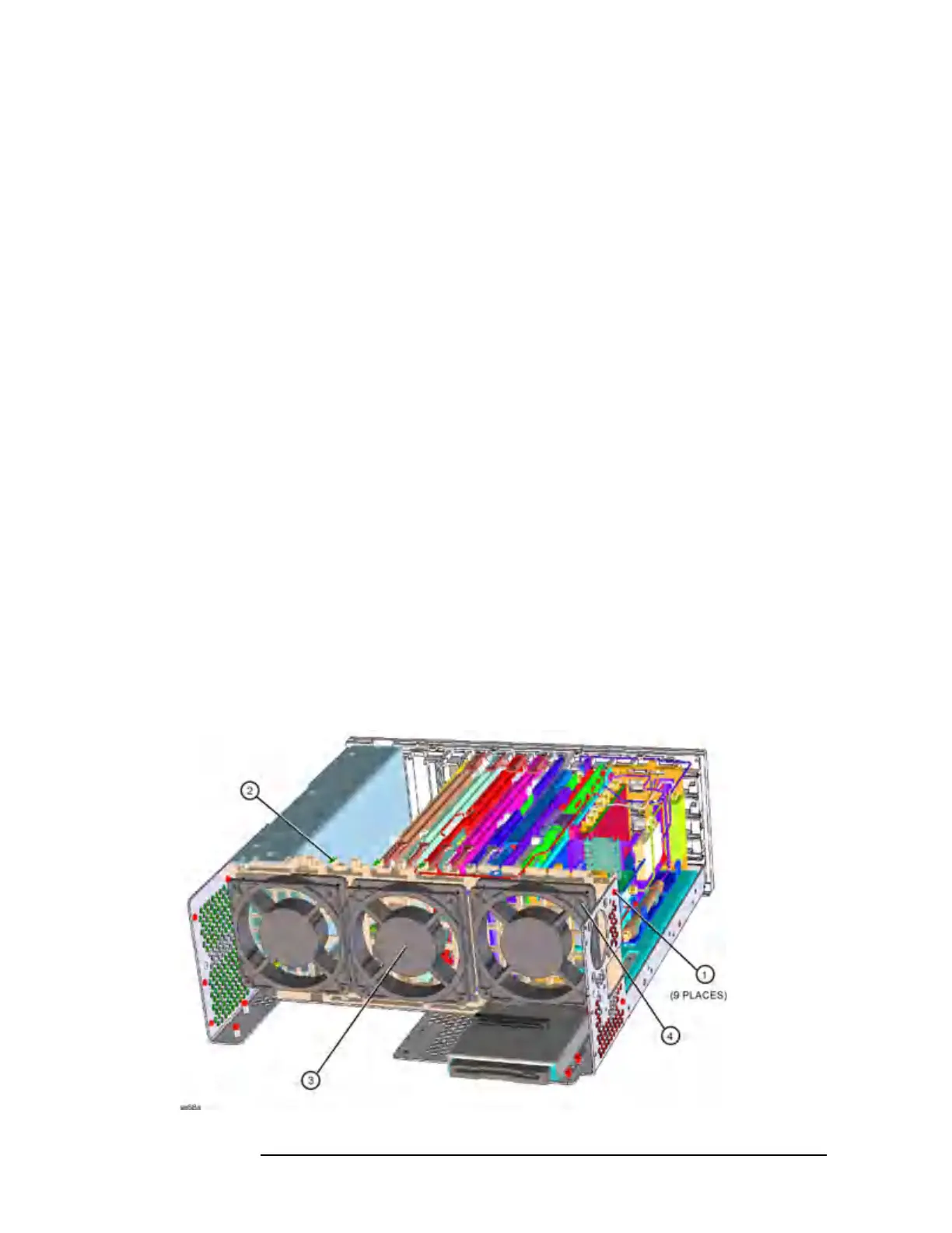
6. Refer to Figure 11-44. Undress the coaxial cables from the cable
guide in the mid-web.
7. Using the T-10 driver, remove the 9 screws (1) that secure the
mid-web/fan assembly (2) to the deck. Note this includes 5 screws
on the bottom of the instrument. Refer to Figure 11-47 on page 383
and remove the screws (1).
8. Unplug the 3 fan connectors from the motherboard.
9. Lift the mid-web/fan assembly from the deck.
Figure 11-44 Mid-Web/Fan Assembly Removal
 Loading...


