EasyManuals Logo
Home>Agilent Technologies>Measuring Instruments>E4448A

Agilent Technologies E4448A Service Guide

Agilent Technologies E4448A
436 pages
To Next Page IconTo Next Page
To Previous Page IconTo Previous Page
Page #388 background imageLoading...
Page #388 background image
388 Chapter 11
Assembly Replacement Procedures
A26A1 DRAM and A26A2 Flash Boards
CAUTION Use ESD precautions when performing this replacement procedure.
Removal
1. Remove the instrument top brace. Refer to the “Top Brace” removal
procedure.
2. Remove the A26 assembly. Refer to the “A26 CPU Assembly”
removal procedure.
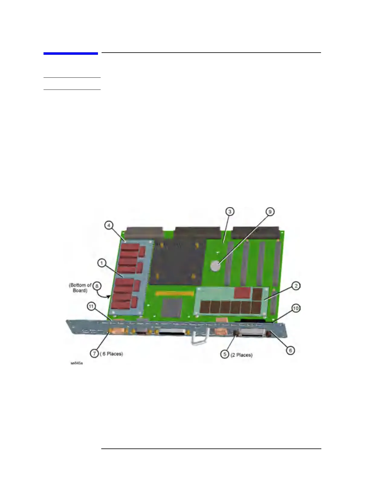
3. Refer to Figure 11-50. Cut the standoffs flush with the top of the
memory board, and carefully pull up on either the A26A1 DRAM
board (1), or the A26A2 Flash board (2) to disengage it from the
CPU assembly.
Figure 11-50 A26A1 and A26A2 Board Removal

Table of Contents

Other manuals for Agilent Technologies E4448A

Questions and Answers:

Question and Answer IconNeed help?

Do you have a question about the Agilent Technologies E4448A and is the answer not in the manual?

Agilent Technologies E4448A Specifications

General IconGeneral
BrandAgilent Technologies
ModelE4448A
CategoryMeasuring Instruments
LanguageEnglish

Related product manuals