Chapter 11 341
Assembly Replacement Procedures
RF Section E4446A, E4447A, E4448A
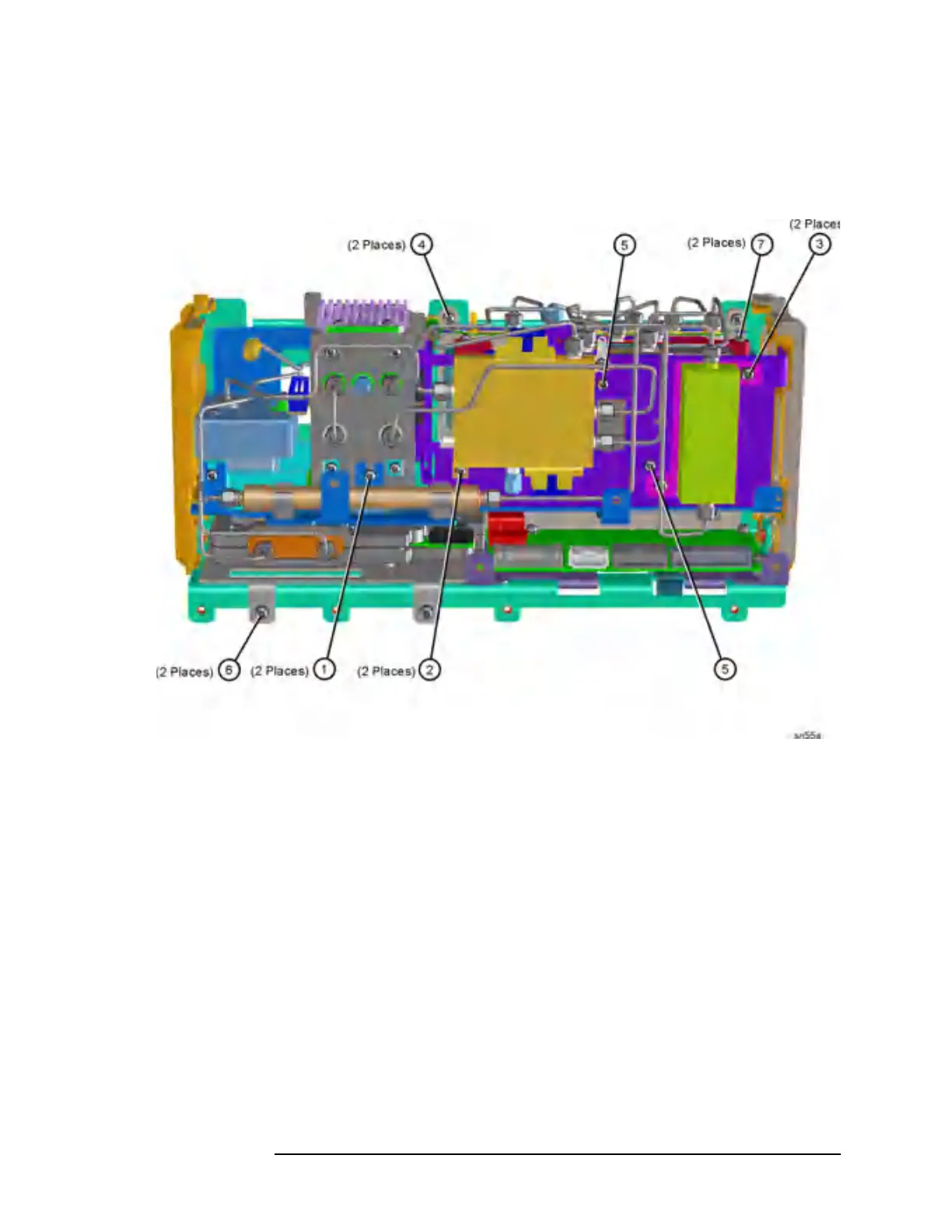
Figure 11-25 RF Section Hardware
A18 YTO and A19 SBTX/RYTHM
Removal
1. Refer to Figure 11-24. Remove the semi-rigid cables, W33, W35,
W36, and W38.
2. Remove the ribbon cables attached to the YTO and SBTX/RYTHM.
3. Refer to Figure 11-25. Using the T-10 driver, remove the 2 screws
(1). Remove the third screw that can be accessed down behind the
YTO, near the Mid Web.
4. Carefully remove the bracket containing the YTO and
SBTX/RYTHM from the RF section.
 Loading...


