Chapter 11 367
Assembly Replacement Procedures
Vertical Board Assemblies (Standard Instrument)
Vertical Board Assemblies
(Standard Instrument)
CAUTION Use ESD precautions when performing this replacement procedure.
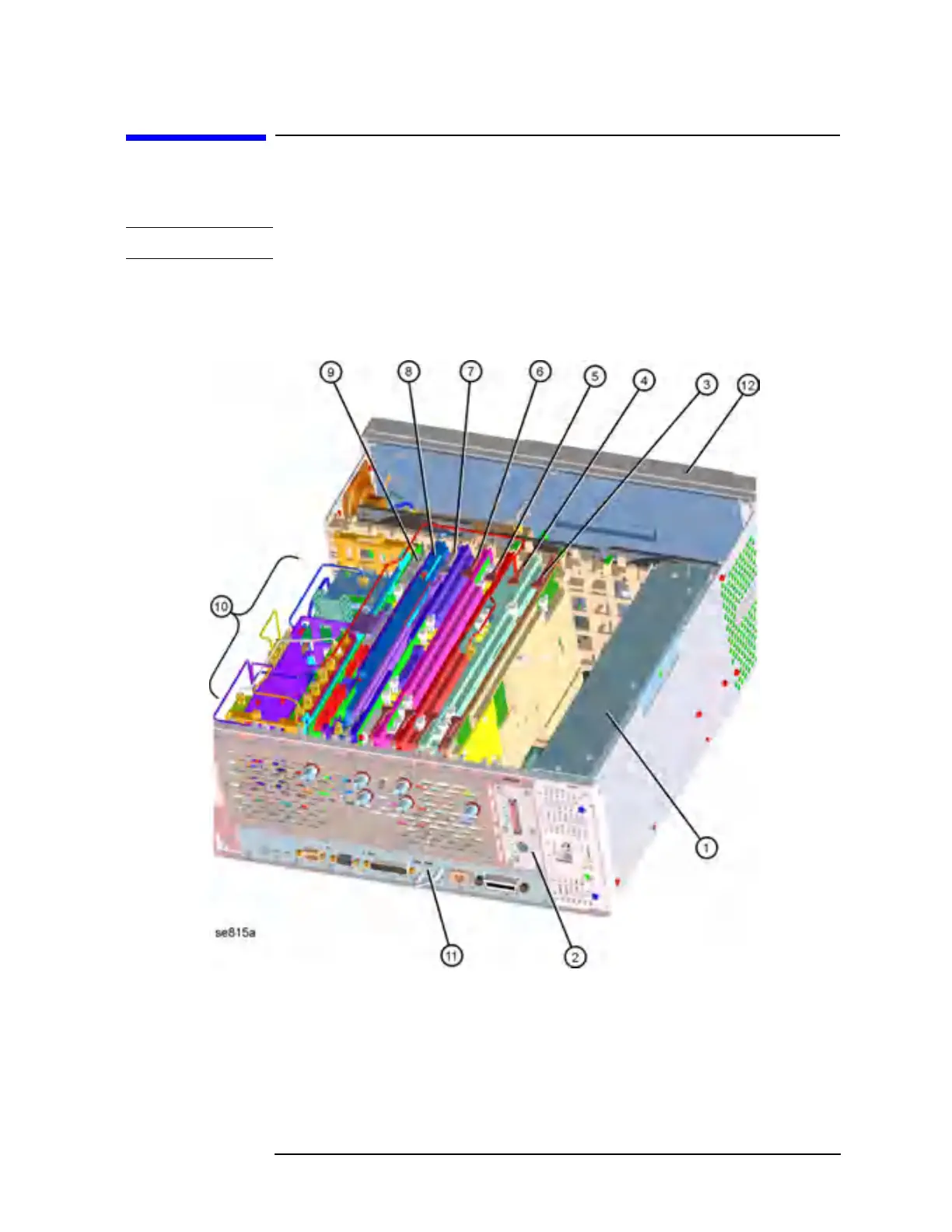
Figure 11-39 shows the location of the vertical board assemblies.
Figure 11-39 Vertical Board Assembly Locations
 Loading...


