392 Chapter 11
Assembly Replacement Procedures
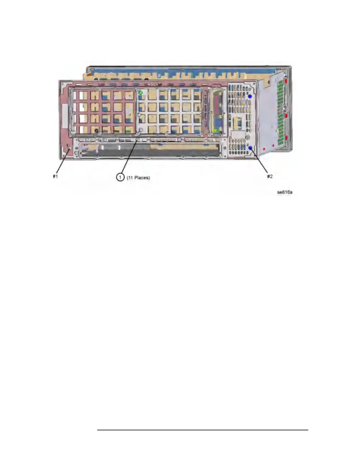
Rear Frame
Figure 11-53 Rear Frame Removal
Replacement
1. Place the rear frame in position on the deck.
2. Using the T-10 driver, replace the 11 screws to secure the rear frame
to the deck. For alignment purposes, tighten the screws marked with
a #1 and a #2 in Figure 11-53. Torque to 9 inch pounds.
3. Replace the rear dress panel and reroute the cables. Refer to Figure
11-51 to reconnect the cables to the correct locations.
4. Using the T-10 driver, replace the 13 screws that secure the dress
panel to the rear frame. For alignment purposes, tighten the screws
marked with a #1 and a #2 (silkscreened on the dress panel) first.
Torque to 9 inch pounds.
5. Replace the A26 CPU assembly. Refer to the “A26 CPU Assembly”
replacement procedure.
6. Replace the A6 SCSI board. Refer to the “A6 SCSI Board”
replacement procedure.
7. Replace the vertical board assemblies and reattach the cables. Refer
to the “Vertical Board Assemblies (Standard Instrument)”
replacement procedure. Refer to Figure 11-51 for the proper dressing
of the cables.
8. Replace the instrument top brace. Refer to the “Top Brace”
replacement procedure.
 Loading...


