Chapter 8 203
Hardware Options
Verifying Option 124, Y-Axis Video Out
Verifying Option 124, Y-Axis Video Out
The following two procedures outline how to verify that the rear panel
video out signal is correct. The first procedure is a quick check of the
0 to 1 V video out signal level that requires only a voltmeter.
The second procedure allows you to view the video out signal on an
oscilloscope and compare it to the PSA screen.
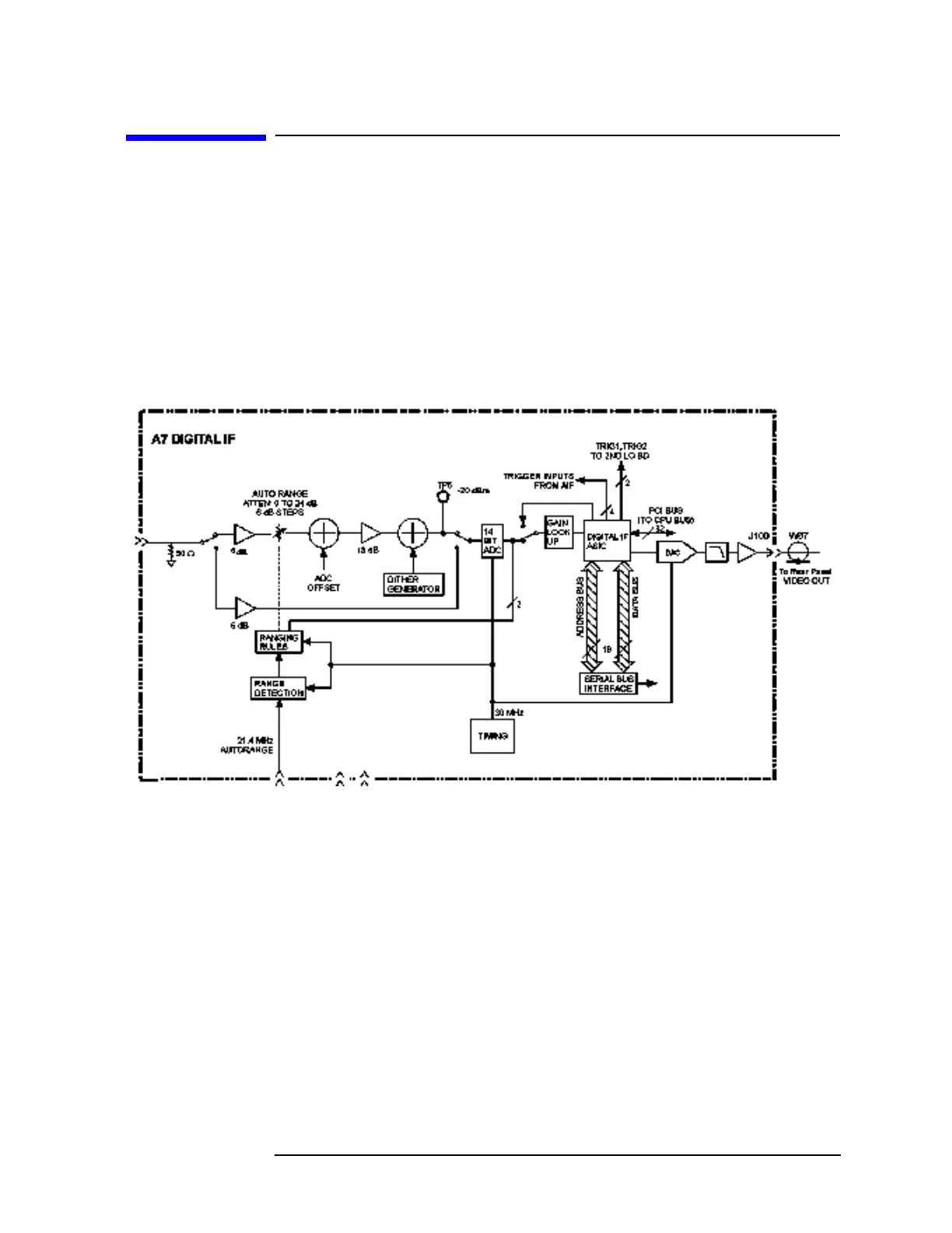
Figure 8-13 shows the block diagram of the optional A7 Digital IF that
supports Option 124.
Figure 8-13 Option 124
Procedure 1 - Quick check of video out level.
Connect a voltmeter to the rear panel Video Out port of the PSA. Set
the voltmeter to measure DC volts.
1. With the instrument is spectrum analysis mode,
Preset the
instrument.
2. Select the internal amplitude reference by pressing
Input/Output,
Input Port, and selecting the Amptd Ref.
3. Tune the analyzer to 50 MHz.
Frequency, 50 MHz.
4. Set the analyzer to 5 dB/div.
Amplitude, Scale/Div, 5 dB
5. Set the analyzer to zero span.
Span, Zero Span.
 Loading...


