352 Chapter 11
Assembly Replacement Procedures
RF Section E4446A, E4447A, E4448A
Option 123 Assemblies
E4446A, E4447A, E4448A
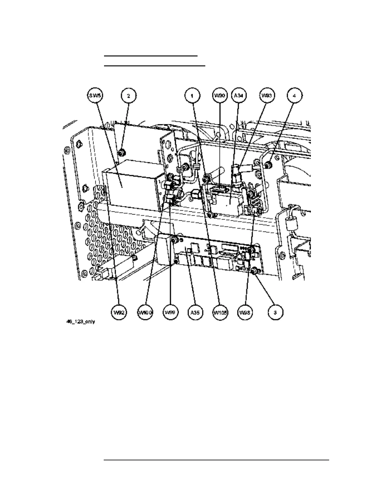
Figure 11-31 Option 123 Assembly and Cable Locations
A34 Mixer
Removal
1. Drop the front frame. See page 314 for instructions.
2. Refer to Figure 11-31. Remove cables W93, W98, W99, and flat flex
cable W90.
3. Remove the three screws (1) that attach the A34 Mixer to the
standoffs.
 Loading...


